


Symptom
Cause
Corrective Action
The fl ame effect will
not start.
Mains plug is not plugged in.
Low water level.
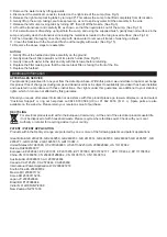
Low voltage connector not connected
properly. (See Fig.5)
The Transducer Unit is not sitting correctly in
the sump
Check plug is connected to wall socket
correctly.
Check that the water tank is full and there is
water in the sump.
Check that the connector is inserted
correctly. (See Fig.5)
Ensure the Transducer in sitting down into
the moulded recess in the sump
The fl ame effect is too
low.
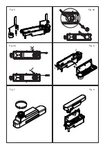
Flame effect control knob is set too low.
(See Fig.10)
The Metal Disc in the transducer might be
dirty (See Fig.14)
The wire from the Transducer Unit is sitting
over the metal disc
Increase level of fl ame by turning Control
knob ‘D’ to the left slowly. (See Fig.10)
Clean the Metal Disc with soft brush
supplied. (See Fig.14) See ‘Maintenance.’ for
a step by step procedure.
Direct the wire to the back of the sump and
make sure it sits into the side slot exiting the
sump.
Unpleasant smell
when unit is used.
Dirty or stale water.
Using unfi ltered tap water.
Clean the unit as described under
maintenance.
Use only fi ltered tap water.
The fl ame effect has
too much smoke.
Flame effect setting is too high.
Turn the fl ame effect Control knob ‘D’ to
the right, about ¼ a turn, at a time. Give the
fl ame generator some time to adjust to the
new setting. (See Fig.10)
Main lamps are not
working and there are
no fl ames or smoke.
There is no water in the water tank
Follow instructions under
Maintenance
, ‘Filling the water tank’.
Check the plug is connected to the wall
socket correctly and that Switch ‘A’ Fig. 10 is
in the ‘ON’ (
I
) position.
Troubleshooting
Содержание Burgate BRG20
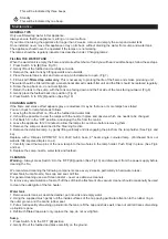
Страница 8: ...33 33 62 39 66 Fig 1 Fig 4 Fig 4a Fig 2 Fig 3...
Страница 9: ...Fig 5 Fig 5a Fig 5b Fig 6 Fig 7 Fig 8...
Страница 10: ...Fig 9 Fig 10 Fig 11 Fig 12 Fig 13 Fig 14...
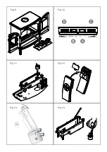
Страница 11: ...Fig 15 Fig 16 Fig 17 REMOTE CONTROL SENSOR 30 60 90...


