


9
Cut the wires from the original motor approximately 2”
•
inches from the motor and strip the sheathing off the
wire end by approximately 1/2” inch.
Cut the end of the wires from the new motor, leaving
•
several inches (approx. 6”) in length from the motor.
Strip the sheathing by approximately 1/2” inch.
Connect the black wire from the original motor and the
11.
black wire from the new motor and attach them using a
twist-on wire connector.
Repeat step 11 for the white wire.
12.
Reassemble in the reverse order as above.
13.
HEATER ASSEMBLY REPLACEMENT
Tools Required:
Phillips screw driver
Flat Head screw driver
WARNINg:
If the fireplace was operating prior to servic
-
ing allow at least 10 minutes for light bulbs and heating
elements to cool off to avoid accidental burning of skin.
WARNINg:
Disconnect circuit power before attempting
any maintenance or cleaning to reduce the risk of elec-
tric shock or damage to persons.
!
NOTE:
This unit is equipped with two heater assem-
blies.
Open the steel curtains (remove glass doors if appli-
1.
cable) on the side where the replacement is required.
Remove the steel curtains by lifting up on the curtain
2.
mounting rod releasing it from the side mounting tab,
and pulling out. Repeat this for both the left and the
right side of the visual opening of the fireplace.
Remove the inside cover mounting screws from the
3.
firebox and remove the cover by lifting it up from the
back, bowing it slightly in the center and pulling out by
one end.
Locate the heater assembly mounted to the top panel
4.
and disconnect the connections noting their original
locations.
!
NOTE:
Using a flat head screwdriver gently pry be
-
tween the end of the connector and the heater to release
the wires.
Remove the two mounting screws and pull forwards to
5.
release the heater assembly from the top cover.
Remove the heater assembly mounting screws and
6.
remove the heater assembly.
Properly orient the replacement heater assembly and
7.
connect all of the wiring connections in their original
locations.
Reassemble in the reverse order as above.
8.
REMOTE CONTROL RECEIvER
REPLACEMENT
Tools Required:
Phillips screw driver
Wire Cutters
Needle Nose Pliers or Slip Joint Pliers
WARNINg:
If the fireplace was operating prior to servic
-
ing allow at least 10 minutes for light bulbs and heating
elements to cool off to avoid accidental burning of skin.
WARNINg:
Disconnect circuit power before attempting
any maintenance or cleaning to reduce the risk of elec-
tric shock or damage to persons.
Starting on the side of the double-sided fireplace where
1.
there are no manual controls.
Open the steel curtains (remove glass doors if appli-
2.
cable).
Using needle nose pliers, release the left steel curtain
3.
from the side panel by slightly opening the retainer
clips on the panel and unhooking the curtain.
Remove the left hand curtain by lifting the rod out from
4.
the left side mounting tab. Once released, lower the rod
and pull it out from the left together with the curtain.
Remove the 2 screws from the log set retaining plate
5.
along the front of the log set and remove the retaining
plate.
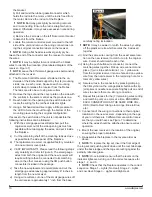
Pull the rear edge of the log set forward by grasping
6.
the ember bed by the sides, pull firmly until the rear tab
pops out from under the back ledge, then lift the logs
out. (Figure 4)
!
IMPORTANT:
Only handle the log-set by the plastic
ember-bed, not the logs themselves.
!
NOTE:
Log-set fits tightly into firebox. Some force may
be necessary to remove.
Locate the remote control receiver housing cover plate
7.
on the left, in the cavity beneath the ember-bed. Re-
move the 2 mounting screws located on the top of the
cover plate and remove it from the firebox.
!
NOTE:
Location of the receiver has very limited space.
It may be helpful to remove the flicker rod and left bracket
to allow for extra work space. They can be removed as fol-
lows:
a) Remove the plastic grommet, which holds the end of
the rod in the bracket. Grasp and turn it ¼ turn, releas-
ing it from the slot in the bracket, and then lift it out of
Figure 5


