Dimension One Spas 01510-1030E Rev A Скачать руководство пользователя страница 1


Содержание 01510-1030E Rev A

Страница 1: ......

Страница 2: ......

Страница 3: ...UB WOOFER COMPARTMENT 13 PRE WIRING FROM EQUIPMENT COMPARTMENT TO SUB WOOFER COMPARTMENT 19 INSTALLATION OF POWER SUPPLY 25 Pre Wire Power Supply 25 Installing Power Supply in Equipment Compartment 28...

Страница 4: ...Export Sonic Immersion System iv...

Страница 5: ...unparalleled sound quality even in the harshest environmental conditions Superior fidelity and low distortion Articulated speaker mount that allows multidirectional capability and if the speakers are...

Страница 6: ...Export Sonic Immersion System Dealer Installation Guide Dealer Installation This section intended for use by authorized dealer personnel only 2...

Страница 7: ...91198 and higher Chairman 91245 and higher Chairman II 91234 and higher Diplomat 91197 and higher Nautilus 91458 and higher Also 91455 Triad 91372 Triad II 91625 an higher Also 91567 Overview of the I...

Страница 8: ...mm drill bit 3 8 inch 9 5 mm drill bit Saber Saw Phillips screwdriver Tape masking electrical duct or packaging in 12 7 mm width Spring loaded punch or other tool s that can be used to mark drilling l...

Страница 9: ...liers Wire Stripper Utility Knife 5 16 7 94 mm Nut Driver or wrench Six inch 15 24 cm square Stapler and Staples Straight Edge Safety Glasses Silicone caulking clear Small Saw Parts List You should ha...

Страница 10: ...iption Qty Item Number This document 1 01510 1030 Amplifier 1 01564 08 Coarse Threaded Drywall Screws 5 01051 06 Template 1 Doc 74 Rev A Power Supply Harness 1 01564 19 Power supply stereo 1 01564 01...

Страница 11: ...3 Sub woofer sub assembly 1 01564 09 Stereo cover marine 1 01564 04 Dual pole antenna 1 01564 05 Preamp stereo cable 2 01570 24 Power supply screw sheet metal SS PH 2 01011 38 Marine cover screws 8 x...

Страница 12: ...the panel where the Satellite Speakers are to be installed Remove Equipment Compartment Panel Warning Possible Electrical Shock Hazard 1 Turn off the main spa circuit breaker located in the disconnec...

Страница 13: ...re 1 Top Side Control 4 The Lower Control is located in the equipment compartment behind the spa panel below the Main Top Side Control 5 Use the screwdriver to remove the equipment compartment panel s...

Страница 14: ...f spa Remove the Sub Woofer Compartment Panel The installation location of the sub woofer compartment will vary from one spa model to another Use Table 4 to locate the compartment on your spa First st...

Страница 15: ...b Woofer Installation Locator Top Side Control Table 4 Model List Model and Number Location of Installation Aurora II and Chairman Top Side Control Chairman II and Aurora XLT Top Side Control Diplomat...

Страница 16: ...on Guide Caliente HP Triad II Aurora HP and Triad Top Side Control 1 Use the screwdriver to remove the spa panel screws Figure 3 Figure 3 Equipment Compartment Panel Screws Note The number of screws t...

Страница 17: ...f you have a spa with wood siding you may skip to Step 2 If your spa has EnviroTect siding you will need to remove the white foam sheeting Figure 4 Figure 4 Removing EnviroTect Sheeting 2 Using a lock...

Страница 18: ...not look like your spa refer to Table 4 1 Sub Woofer Plug Figure 6 Sub Woofer Plug 3 Once the plug is exposed Figure 6 use a screwdriver to punch holes in the foam large enough to insert your hands a...

Страница 19: ...e pliers to remove the large staples in the bottom rail where the plug was removed 5 Remove all remnants of the plastic bag inside the compartment where the plug was removed This will expose the elect...

Страница 20: ...on Guide 1 Electrical Conduit Before Trimming Figure 8 Electrical Conduit 6 Using a non ratcheting PVC pipe cutter trim the electrical conduit flush with the foam wall Figure 9 1 Electrical Conduit Af...

Страница 21: ...cation of the conduit in the spa Using a1 inch 3 8 cm hole saw drill a hole for the conduit Figure 10 Figure 10 Drilling Hole for Cables 8 Try to place the sub woofer compartment into the space where...

Страница 22: ...Sonic Immersion System Dealer Installation Guide 1 Bottom Edge of Frame Figure 11 Edge of Frame 9 A properly positioned sub woofer compartment is shown in Figure 12 Figure 12 Properly Installed Sub Wo...

Страница 23: ...mpartment to the frame Figure 13 with 5 1 2 54 cm coarse threaded drywall screws P N 01051 06 provided in hardware package Figure 13 Attaching to Frame Pre Wiring from Equipment Compartment to Sub Woo...

Страница 24: ...te and two red RCA connectors on both ends P N 01570 24 Locate the three branched harness assembly P N 01564 20 One branch will be considerably longer than the other two 3 Attach the preamp stereo cab...

Страница 25: ...rag to give them a light coating of lubricant Figure 16 Figure 16 Applying Lubricant to Cables 5 Now pull them through the conduit from the equipment compartment to the sub woofer compartment Figure 1...

Страница 26: ...than necessary Make sure that when the wires are connected to the amplifier that the amplifier can be moved out to make adjustments Using a wire stripper strip approximately inch 1 27 cm of insulator...

Страница 27: ...ctors One is copper colored and the other is silver Strip approximately inch 1 27 cm of insulator from each wire and twist each to form a tight bundle Connect the copper colored wire to the terminal m...

Страница 28: ...and 22 1 Line Level Input 2 Mode Control 3 Bass Boost Control 4 HP LP Crossover Control 5 Gain Controls 6 High Pass Controls Figure 21 Terminals and Controls 1 Channel 1 used for Satellite Speakers 2...

Страница 29: ...on 13 Set HIGH PASS CH 1 and CH 2 to the 200 HZ positions 14 Set CH 1 to HP position and CH 2 to LP position Installation of Power Supply Pre Wire Power Supply Locate the power supply kit that contain...

Страница 30: ...White Figure 24 Connector Wire Configuration 1 Connect the wires from Row 1 120 V Supply to the power supply as follows black wire to the terminal marked AC L the white wire to terminal marked AC N a...

Страница 31: ...wire to terminal marked DC 1 Black Wire 2 Red and Yellow Wires Figure 26 Connecting Wires to Stereo and 12 V Supply Terminals on Power Supply 3 Connect the wires coming from Row 3 Amplifier as follow...

Страница 32: ...or CE spas for your location 1 Voltage Switch Figure 28 Voltage Switch on Back of Power Supply 2 Locate two 8 x 1 27 cm Pan head screws P N 01011 38 in the power supply kit The power supply has two ho...

Страница 33: ...r and Lower Screw Holes Figure 29 Location of Attachment Holes on Power Supply 3 Locate the connector on the harness assembly that matches the one that you just installed on the power supply and conne...

Страница 34: ...ove lower control box cover Insert these wires through the hole in the bottom of the lower control box Figure 31 1 Wires Inserted through Hole in Bottom of Lower Control Box Figure 31 Inserting Wires...

Страница 35: ...control box over the screw replace 5 16 7 9 mm nut and secure with 5 16 7 9 mm nut driver or wrench 4 Connect the white and black wires to the pins as outlined in Table 5 Table 5 Pin Connectors Board...

Страница 36: ...ends on the model of the spa The following steps will guide you through the process of determining the installation location 1 Refer to Figure 33 Measure distances A and B 1 Detail of Stereo Recess Ar...

Страница 37: ...ents determined in Step 1 and insert them into the following formula Distance A ______ Distance B _______ A 1 2 54 cm Vertical Position VP _________ B 1 91 cm Horizontal Position HP ________ 3 Now pro...

Страница 38: ...m of Panel 2 Panel Lay Face Up 3 Top of Panel Figure 34 Measuring Vertical Distance 2 Using measurement obtained for Horizontal Position HP measure from side of panel see Figure 35 and mark spot with...

Страница 39: ...v A 4 Align the upper right corner of the template with the mark on the panel Use a center punch to mark the spot Figure 36 Figure 36 Aligning Template 5 Square up the template on the panel and use th...

Страница 40: ...the drilling centers will prevent the drill bit from wandering 1 Hole Locations Figure 38 Hole Locations 8 Using a saber saw cut out the rectangular piece from the panel 9 Depending on where the hole...

Страница 41: ...Figure 40 1 Door Assembly 2 Bezel Figure 40 Bezel and Door Assembly 2 Place the door assembly in the cutout Make certain the door will open and close freely Door should open from bottom 3 Locate 4 8...

Страница 42: ...r s manual for directions on how to install this sleeve Once the CD player mounting sleeve is installed in the panel proceed to the following paragraph Installation of Panel and CD Player 1 Place the...

Страница 43: ...ble long branch of main harness to power supply connector on CD player Connect Channel 1 preamp stereo cables RCA cable to FRONT connectors on the CD player and the Channel 2 cables to the REAR connec...

Страница 44: ...with the top triangular portion of the hinge butting up against the lower edge of the overhanging spa lip 2 Remove the protective caps from the hinge screw holes and using a center punch mark the loca...

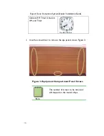
Страница 45: ...Export Sonic Immersion System Dealer Installation Guide 1 Caps in Place Figure 44 Protective Caps in Place 41...

Страница 46: ...connectors on one end 3 Using a Cable Tyes and Cable Mounts P N 01200 006 and 01200 005 attach the wires to the frame in the approximate location of the speakers directly below the edge of the spa se...

Страница 47: ...hen pushed all the way up under the lip the wire or cable will rest safely on the lip of the spa wall 2 Cable or Wire 3 Spa Shell s Lip 4 Wooden Ruler or Paint Stir Stick 5 Install Wire or Cable Under...

Страница 48: ...ach the wire to the wood until you reach the sub woofer compartment Figure 47 1 Speaker Wires Coming from Satellite Speakers Figure 47 Satellite Speaker Wires in Sub Woofer Compartment 6 Trim any exce...

Страница 49: ...ure 48 Connecting Satellite Speaker Wires to Amplifier 8 Now connect the wires coming from the sub woofer compartment to the satellite speakers The wires from the speakers have male connectors and the...

Страница 50: ...rsion System Dealer Installation Guide 9 Place the panel back on the spa and secure with screws The finished installation should appear as in the pictures shown in Figure 50 Figure 50 Completed Speake...

Страница 51: ...the speakers have been installed and the amplifier has been adjusted it can be secured to the frame Figure 51 with dry wall screws supplied in the kit P N 01051 06 Figure 51 Securing Amplifier to the...

Страница 52: ......

Страница 53: ......

Страница 54: ...Part No 01510 1030E Rev A 2002 Dimension One Spas...

Отзывы: