DIGITAL YACHT LTD
AIT1000 Quick Start Guide
Installation Step 2
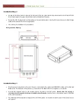
Access to the fixing holes is achieved by removal of the two green decal strips down each side of the AIT1000.
Once fixed in place, the green decal strips can be clicked back in place.
Secure the AIS Transponder to a flat surface in the selected location. Use four M4 wood screws or other fixings
suited to the material the unit is being fixed to.
The unit may be installed in any orientation
Fixing location drawing
Installation Step 3
Provide power connections to the unit. Power is connected to the eight core PWR/DATA cable on the Red and
Black wires. The Red wire is the positive (+) connection. The Black wire is the negative (-) connection.
Connect the stripped wires to the nearest source of primary 12V DC power.
Ensure that the supply is
connected via the supplied 3A fuse or suitable circuit breaker.
Add the fuse in the positive power connection
to the unit if necessary.
The AIS Class B Transponder is designed for a 12V DC system. A converter should be used if the vessel uses a
24V system.


