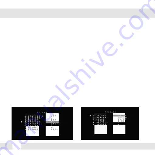
Digital Watchdog DWC-V6763TIR Скачать руководство пользователя страница 28

28

SPECIAL (CONT.)

PRIVACY

 - SELECT: The camera supports up to 4 separate privacy zones. Select which one to adjust.

 - DISPLAY: There are three types of privacy masks you can apply. Select from MOSAIC, INV., 

  or COLOR. 


- MOSAIC: The privacy mask will appear as a mosaic over the camera’s image.


- INV.: The privacy mask will appear as a negative of the image behind it, reversing 


the colors and brightness. 


- COLOR: The privacy mask will appear as a block of color according to the settings 


in the COLOR menu. 

To adjust the zone’s position and size, once the type of mask is selected, use the joystick 

  controller on the camera’s board to adjust the zone’s position. Press the enter key and use the 

  joystick controller to adjust the zone’s size.

 - COLOR: If COLOR is selected under the display options, set the color for the motion zone. 

Select from white, black, red, blue, yellow, green, cyan, or user. If user is selected, the mask’s 

color will default to dark green. 

 - TRANS: Set the zone’s transparency. The lower the number, the more transparent the zone 

will be.

 - DEFAULT: Reset the motion detection settings to their default values.

Содержание DWC-V6763TIR

Страница 1: ...12 15 ABOUT MANUAL Before installing and using the camera please read this manual carefully Be sure to keep it handy for future reference Analog High Definition Outdoor Dome Camera DWC V6763TIR ...

Страница 2: ...erature may rise to high levels Cleaning To remove dirt from the case moisten a soft cloth with a soft detergent solution and wipe Mounting Surface The material of the mounting surface must be strong enough to support the camera FCC COMPLIANCE This equipment has been tested and found to comply with the limits for a Class B digital device pursuant to part 15 of the FCC rules These limits are design...

Страница 3: ... Dimensions Inside the Box Surface Mount Installation instructions Connecting to Monitors 13 Corner Mount Installation Instructions 12 Pendant Mount Installation Instructions 11 Wall Mount Installation Instructions 10 Junction Box Installation Instructions Control Board 4 5 6 7 8 9 14 16 Adjusting the Camera Axis 15 17 32 33 34 35 36 37 Adjusting the Camera Angle ...

Страница 4: ...IR with Intelligent Camera Sync 100ft Range Smart DNR 3D Digital Noise Reduction Highlight Masking Exposure HME True Day Night Mechanical IR Cut Filter Secondary Video BNC Output While UTP in use Programmable Privacy Zones Auto Gain Control AGC Back Light Compensation BLC Dynamic Range Compressor DRC Reveals Low Light Detail Auto White Balance AWB IP66 Certified Weather Resistant ...

Страница 5: ...PARTS DESCRIPTION 7 8 1 BNC Cable DC12V Cable Bottom Case Camera Gimbal Upper Case Dome Cover 2 3 4 6 5 Cover Screws x4 Side Port for Cabling 6 1 3 5 2 4 7 8 5 ...

Страница 6: ...6 DIMENSIONS IN MILLIMETERS IN 47 0 1 9 144 0 5 7 61 8 2 4 145 0 5 7 117 0 4 6 125 0 4 9 ...

Страница 7: ...mplate 4 Machine Screws and 4 Dry Wall Anchors Secondary Video BNC Cable L Key 10 08 ABOUT MANUAL Before installing and using the camera please read this manual carefully Be sure to keep it handy for future reference Analog High Definition Outdoor Dome Camera DWC V6763WTIR ...

Страница 8: ...res through and make connections 3 Using the four 4 included screws mount and secure the camera to the wall or ceiling 4 Adjust the camera s Pan and Tilt and Lens See pages 15 16 for more information 5 Use the joystick to adjust the OSD menu See pages 17 28 for more information 6 Attach the camera housing to the camera base using the assembly screws ...

Страница 9: ...l anchors and machine screws to mount the junction box and rubber gasket to the wall Insert wires through the wall and make the appropriate connections Attach the camera to the junction box using the machine screws Attach the camera housing to the junction box using the assembly screws 1 2 3 4 5 ...

Страница 10: ...sert the wires from the camera through the wall mount housing Attach the camera to the wall mount housing Use the mounting template to make pilot holes Use the dry wall anchors and machine screws to attach the assembly to the wall Attach the camera housing to the fixture 1 2 3 4 5 ...

Страница 11: ...ant mount Slide the wires from the camera through the pendant mount Attach the camera to the pendant mount using the machine screws Attach the camera housing to the fixture Use the mounting template to make pilot holes Mount the camera assembly to the ceiling using wall mount anchors and machine screws 1 2 3 4 5 6 ...

Страница 12: ...k to see all parts are in the box Attach the two compression fittings to the corner bracket Attach the wall mount to the corner bracket with the 4 machine screws Attach the assembly to a wall corner with dry wall anchors and machine screws 1 2 3 4 ...

Страница 13: ...he diagram below to connect to a Monitor or CRT Monitor properly 12VDC Monitor CCTV Monitor Vvideo Output Right Left Up Down Second Power Connection 12VDC All cameras are equipped with a second video output for on site configuration ...

Страница 14: ...14 CONTROL BOARD Remove the camera s cover dome to access the OSD joystick controller Use the Joystick to control the camera s OSD options 1 2 ...

Страница 15: ...ocated on the bottom of the camera counter clockwise to zoom in or clockwise to zoom out Adjust the focus the same way as described above AFTER the desired zoom position is established 1 2 Follow the instructions provided below to make any lens adjustments ZOOM FOCUS Zoom Focus Wide Tele Far Near ...

Страница 16: ...16 ADJUSTING THE CAMERA GIMBAL 1 Rotation 360º 2 Panning 360º 3 Tilting 70º IR LED ...

Страница 17: ... BRIGHTNESS DRC 1 100 OFF AUTO ON 0 8 AGC STAR LIGHT HME AREA DISPLAY BLACK MASK LEVEL MODE DEFAULT RETURN BLC 3DNR RETURN MANUAL AUTO AUTO 1 30 1 50000 X2 X30 0 15 OFF AUTO X2 X30 MANUAL LEVEL AREA DEFAULT RETURN LOW MIDDLE HIGH LOW MIDDLE HIGH FREEZE MIRROR NEG IMAGE RETURN SELECT 1 4 ADJUST DEFECT BLACK DPC WHITE DPC LIVE DPC MOTION SELECT 1 4 EXPOSURE AUTO COLOR B W EXT AGC CDS BURST IR SMART ...

Страница 18: ...cally LIMIT If MANUAL is selected the camera s iris can be adjusted manually using the LIMIT value DC DC lens mode allows you to setup the camera for indoor or outdoor modes If DC is selected adjust the following options MODE Select from INDOOR or OUTDOOR IRIS SPEED Set the reaction speed of the camera s iris If OUTDOOR mode is selected you can adjust the minimum and maximum shutter speed By defau...

Страница 19: ... low light conditions A higher level AGC setting makes the images brighter however it could increase the amount of noise STARLIGHT Automatically activates slow shutter function when the image is too dark OFF AUTO High values are not recommended as they may causes the image to lag x2 x30 To adjust the STAR LIGHT values select AUTO and enter the sub menu Starlight menu cannot be controlled if the SH...

Страница 20: ...stment DEFOG Allows the camera to process a scene that is obscured by fog or weather conditions and provides a visibly improved image POS SIZE Set the location and size of the defog mask Use the joystick controller on the camera s board to adjust the De Fog zone s position Press the enter key and use the joystick controller to adjust the zone s size GRADATION Sett the DEFOG level from 0 2 The high...

Страница 21: ...different HME zones Select which zone to setup DISPLAY For the selected zone select ON to adjust its position and size Use the joystick controller on the camera s board to adjust the zone s position Press the enter key and use the joystick controller to adjust the zone s size BLACK MASK Select whether the HME mask will display in black on the camera s view LEVEL Set the working range of the HME Th...

Страница 22: ...this function press the ENTER key for five 5 seconds MANUAL Control the white balance manually by changing RED and BLUE RED Adjusts the low color temperature in the image between 0 100 The default value is 42 BLUE Adjusts the low color temperature in the image between 0 100 The default value is 40 AWB Auto White Balance Control mode compensates for color temperature changes lower than 2500Ko and h...

Страница 23: ... day mode by the AGC value When the camera detects AGC levels beyond the set threshold it will switch from B W to color N D Delay AGC Set a delay for the camera when switching from night to day mode For cameras with IR LED Built in D N Threshold CDS Set when the camera switches from day to night mode The lower the value the camera will require less light more darkness to switch to Night Mode D N D...

Страница 24: ...n the camera s board to adjust the zone s position Press the enter key and use the joystick controller to adjust the zone s size EXT The Day night settings are set according to a CDS sensor in an external IR LED board D N Delay Set a delay for the camera when switching from day to night mode N D Delay Set a delay for the camera when switching from day to night mode EXT LED AUTO The LEDs are enable...

Страница 25: ... 2DNR Set the Digital Noise Reduction values for general illumination Select from LOW MIDDLE HIGH If the 2DNR settings are set to HIGH image sharpness may be affected 3DNR Set the Digital Noise Reduction values for very low light situations Select from LOW MIDDLE HIGH If the 3DNR settings are set to HIGH lagging issues may appear when motion occurs ...

Страница 26: ... DISPLAY For the selected zone select ON to adjust its position and size Use the joystick controller on the camera s board to adjust the zone s position Press the enter key and use the joystick controller to adjust the zone s size SENSITIVITY Set the camera s sensitivity to motion The higher the value the more sensitive the camera is to motion COLOR Set the color for the motion zone Select from gr...

Страница 27: ...d 3 BLOCK show the area where motion is detected as a solid block 4 OUTLINE Show the area where motion is detected as an outline only OSD VIEW If enabled ALARM will appear on the screen when motion is detected ALARM OUT The camera supports 3 3V alarm output When motion is detected an alarm output can be triggered if enabled TIME Set the dwell time after motion is detected Values are in seconds ...

Страница 28: ...rding to the settings in the COLOR menu To adjust the zone s position and size once the type of mask is selected use the joystick controller on the camera s board to adjust the zone s position Press the enter key and use the joystick controller to adjust the zone s size COLOR If COLOR is selected under the display options set the color for the motion zone Select from white black red blue yellow gr...

Страница 29: ...e level of Live DPC based on the AGC levels BLACK DPC POS SIZE Set the size and position for the DPC Zone Use the joystick controller on the camera s board to adjust the zone s position Press the enter key and use the joystick controller to adjust the zone s size START Press START to begin the DPC test The screen will get bright and compensate for the black defect DPC VIEW Show the Defect pixels w...

Страница 30: ...ill get bright and compensate for the black defect DPC VIEW Show the Defect pixels which have been compensated LEVEL Set the range of DPC application AGC Set the value level for AGC while DPC is on SENS UP Sent the value level of Sens Up while DPC is on RS485 CAM ID Set the camera s ID from 0 255 ID DISPLAY Select to show or hide the camera ID on the screen BAUDRATE Set the camera s baudrate Selec...

Страница 31: ...s darker MONITOR Adjust the camera s signal according to the monitor you are using LCD Mode If using an LCD monitor adjust the following settings GAMMA Set the gamma level from 0 45 1 00 0 55 is default setting BLUE GAIN Set the blue levels form 0 100 RED GAIN Set the red levels form 0 100 CRT Mode If using an CRT monitor adjust the following settings BLUE GAIN Set the blue levels form 0 100 RED G...

Страница 32: ...made to the camera s settings and exit the OSD menu NOT SAVE Exit the OSD menu without saving any changes made to the camera s settings RESET The camera s settings will be reset to their factory default values once you exit the OSD menu ...

Страница 33: ...is connected securely Check the lens iris adjustment at the camera s OSD menu Check the power supply and make sure the camera has the proper voltage and current Check the clear dome cover and the lens for dirt or fingerprints Use a soft cloth and gently clean Check the lens manual focal and zoom adjustment The use of a field test monitor is recommended TROUBLESHOOTING 33 ...

Страница 34: ...h Friday from 9 00AM to 8 00PM Eastern Standard Time A purchase receipt or other proof of the original purchase date is required before warranty service is rendered This warranty only covers failures due to defects in materials and workmanship which arise during normal use This warranty does not cover damage which occurs in shipment or failures which are caused by products not supplied by the Warr...

Страница 35: ...llow the exclusion or limitation of incidental or consequential damages or limitations on how long an implied warranty lasts so the exclusions or limitations listed above may not apply to you This warranty gives you specific legal rights and you may also have other rights that vary from state to state If the problem is not handled to your satisfaction then write to the following address Digital Wa...

Страница 36: ...H x 1080 V Scanning System Progressive scan Frequency 60Hz 50Hz Signal Technology 2 0 Megapixel AHD Synchronization Internal Resolution 1920x1080 1080p Minimum Scene Illumination F1 4 30IRE 0 5Lux Color F1 4 30IRE 0 Lux B W S N Ratio 55dB Video Output AHD 1080p30fps 720p60fps 720p30fps Shutter Speed 1 30 25 1 30 000 Backlight OFF BLC HME STAR LIGHT OFF x2 x30 ...

Страница 37: ... Non Condensing IP Rating IP66 Weather Resistant Other Certifications FCC CE ROHS OPERATIONAL CONT Housing Material and Dimensions Aluminum 145 x 108 8 mm 5 7 X 4 28 in Weight 1 65lbs 37 Digital Noise Reduction Off Low Middle High White Balance Auto Push Manual AWB Day and Night Auto Color B W EXT Auto Gain Control 0 15 Motion Detection Yes Privacy Zones 4 Privacy Zones Sharpness 0 10 Gamma 0 45 1...

Страница 38: ...MEMO 38 ...

Страница 39: ...39 MEMO ...

Страница 40: ...5436 W Crenshaw St Tampa FL 33634 Tel 866 446 3595 813 888 9555 Fax 813 888 9262 www Digital Watchdog com technicalsupport dwcc tv Technical Support Hours Monday Friday 9 00am to 8 00pm EST ...

Отзывы: