Digital Watchdog DWC-B1365T Скачать руководство пользователя страница 8

 8

S

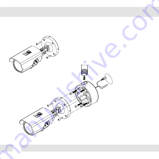
URFACE MOUNT INSTALLATION INSTRUCTIONS*

Use the 4 mounting screws to install the camera on the 

wall or ceiling.

Then, follow the next step on pages 9-12.

NPT 3/4” Pipe

*Installation Using a Junction Box

*Note: Electrical junction box and required screws are sold separately.

Содержание DWC-B1365T

Страница 1: ...07062012 ABOUT MANUAL Before installing and using the camera please read this manual carefully Be sure to keep it handy for future reference PIXIM Bullet Camera DWC B1365T ...

Страница 2: ...rature may rise to high levels Cleaning To remove dirt from the case moisten a soft cloth with a soft detergent solution and wipe Mounting Surface The material of the mounting surface must be strong enough to support the camera FCC COMPLIANCE This equipment has been tested and found to comply with the limits for a Class B digital device pursuant to part 15 of the FCC rules These limits are designe...

Страница 3: ...enu Troubleshooting Warranty Information Specifications Features Parts and Descriptions Dimensions Inside the Box Mount Installation Instructions Connecting to Monitors Control Board Adjusting the Camera Lens 4 5 6 7 8 9 10 11 13 24 25 26 27 28 29 Adjusting the Camera Angle 12 ...

Страница 4: ...Wide Dynamic Range Ultra Low Light Sensitivity Smear Canceling Circuit AGC BLC AWB Programmable Privacy Zones 6 Motion Detection OSD Menu with Built in Joystick IP66 Certified Weatherproof No Fog or Condensation under Any Weather Condition Auto Sensing 12VDC 24VAC with Line Lock Secondary Video BNC Output Ball Neck Bracket Simple Camera Positioning External Lens and OSD Control ...

Страница 5: ...7 8 13 12 10 9 3 11 1 Front Case Zoom Focus Housing Sunshield Lens Rear Case Control Board Control Cap 2 3 4 5 6 8 Double Arm Bracket Second Video BNC Output Connector Power Input Connector Dual Voltage Assembly Screw Mounting Screw Set Screw 9 10 11 12 13 7 ...

Страница 6: ...6 DIMENSIONS IN MILLIMETERS IN 230 9 06 86 5 3 41 122 4 80 96 5 3 80 68 0 2 68 68 0 2 68 78 0 3 07 5 0 0 2 96 0 3 78 ...

Страница 7: ... Template 4 Machine Screws and 4 Dry Wall Anchors Secondary Video BNC Cable L Key Double Sided TORX T20 Hex Key ABOUT MANUAL Before installing and using the camera please read this manual carefully Be sure to keep it handy for future reference Bullet Camera DWC B1363D DWC B1363TIR ...

Страница 8: ...RUCTIONS Use the 4 mounting screws to install the camera on the wall or ceiling Then follow the next step on pages 9 12 NPT 3 4 Pipe Installation Using a Junction Box Note Electrical junction box and required screws are sold separately ...

Страница 9: ...roperly 12VDC 24VAC Monitor CCTV Monitor Second Video Output Right Left Up Down Power Connection 12VDC 24VAC Dual Voltage Auto Polarity Detection and Protection All cameras are equipped with a second video output for on site configuration 9 CONNECTING TO MONITORS ...

Страница 10: ...SD menu Secondary Connector Video Output Connector for On Site Configuration CONTROL BOARD Remove clear plastic ring from the control cap Turn control cap counter clockwise until cap separates completely from the camera body 1 2 ...

Страница 11: ... THE CAMERA LENS FOCUS ZOOM To adjust the field of view use the L Key to turn the zoom screw located on the bottom of the camera counter clockwise to zoom in or clockwise to zoom out Adjust the focus the same way as descriped above AFTER the desired zoom position is established 1 2 ...

Страница 12: ...CAUTION 12 ADJUSTING THE CAMERA ANGLE Do not rotate more than 360o Do not unnecessarily twist too many times 1 2 ...

Страница 13: ...TION ZONES 1 1 2 1 3 1 4 ADJUST ZONE 1 ADJUST ZONE 2 ADJUST ZONE 3 ADJUST ZONE 4 RETURN EXIT JUMP SAVE EXIT EXIT PRIVICY MASK OFF ON AREA 1 6 RETURN MASK COLOR WHITE BLACK RED EXIT JUMP SAVE EXIT EXIT PC CONTROL CAM ID 1 255 PROTOCOL BAUDRATE RETURN TITLE OFF ON LANGUAGE ENGLISH DEUTSCH FRANCAIS ITALIAN ESPANOL DUTCH OMNI LENS ALARM READ TIEM ALRAM ZOOM STAND BY RETURN FLUORESCENT OFF CRR CRR2 DIG...

Страница 14: ...he maximum you get the clear image Set the lens Focus Meter to maximum See above for more information DC GAIN is to adjust Iris speed 0 255 It is recommended to set the AUTO Gain to 120 AI THOLD is to define gain level 48 60 DC mode is supported for Auto iris Varifocal lens Set the Focus Meter to maximum MANUAL Manual iris or Fixed board lens DC Auto iris Varifocal lens ...

Страница 15: ...Auto Exposure Set AE PREFERENCE depending on the environment in which the camera is installed Select from the following options INDOOR OUTDOOR Backlight compensation prevents subjects in defined areas from appearing too dark when backlighting is present If BLC is enabled adjust the SHADOW GAIN as desired ...

Страница 16: ... options LOW NORMAL MEDIUM Factory Default HIGH CUSTOM If CUSTOM is selected adjust the Bias Limit as you wish BIAS 30 30 Decide the WDR level in the range of LIMIT The higher the number the stronger the WDR adjustment LIMIT 0 36 Decide the range of WDR effect level 0 means WDR is OFF The higher the number the stronger the WDR will be WDR Wide Dynamic Range WDR OFF WDR ON ...

Страница 17: ...from X2 30FPS X64 x2 30FPS is the default EXPOSURE EXP Auto Gain Control automatically adjusts the video gain to enhance picture brightness in low light conditions The higher number the better sensitivity However higher settings mean more digital noise in the image Select one of the options LOW MEDIUM HIGH Factory Default Note Increase the setting may cause the image to lag ...

Страница 18: ...e s top border further up e Moving the joystivk down will move the zone s bottom border further down 4 Press the joystick again The zone s borders will appear red Use this option to reduce the size of the zone a Moving the joystick to the right will move the zone s left border further to the right b Moving the joystivk to the left will move the zone s right border further to the left c Moving the ...

Страница 19: ...ar R GAIN 20 20 Adjusts the amount of red in the image The higher the number the image will appear red The lower the number the image will appear green B GAIN 20 20 Adjusts the amount of blue in the image The higher the number the image will appear blue The lower the number the image will appear yellow PUSH LOCK Pushlock is to fix the white balance based on current lighting AWC Auto White Balance ...

Страница 20: ... W 0 60 Adjusts the light level at which the camera switches from day color to night B W mode The higher the number the lower the light level E LEVEL B W Color 0 60 Adjusts the light level at which the camera switches from night B W to day color mode This number should be lower than the value of COLOR B W above BW AGC 0 60 You can fix the Gain levels when the camera switches between Color and B W ...

Страница 21: ...tion D ZOOM Select the desired gamma level 25 100 45 is default 3D DNR reduces the noise on the screen in low light conditions and allows for clearer images even at night Select from the following options OFF LOW MEDIUM HIGH The digital zoom function zooms to the center of the image by default Set the Zoom level from 1 X8 This menu also allows you adjust the camera s Pan and Tilt EXIT_JUMP Go to t...

Страница 22: ... border further up e Moving the joystivk down will move the zone s bottom border further down 4 Press the joystick again to reduce the zone s size The zone s borders will appear red a Moving the joystick to the right will move the zone s left border further to the right b Moving the joystivk to the left will move the zone s right border further to the left c Moving the joystivk up will move the zo...

Страница 23: ... joystick Left and Right to adjust the width of the mask 6 Move the joystick Up and Down to adjust the height of the mask NOTE when adjusting the size of the mask the top and left borders of the mask will remain stationary Only the right and bottom borders of the mask will move to adjust the mask s size 7 If you have enabled multiple masks press the joystick again to remain in edit mode and move t...

Страница 24: ...L INT1 INT2 SYNC to 50 00Hz Select INTERNAL if camera uses DC power or if L L is not required Please note this setup option is only for NTSC version Consult your installer for additional information and assistance with configuration Select L L to syncronize video signals when two or more cameras are using AC power in a switching system INT1 INT2 LL Line Lock ...

Страница 25: ...up to 8 characters long To edit the camera s title move the joystick to the right The 1st letter will be highlighted Move the joystick left and right to select the desired character Press the joystick to move to the next space and repeat as necessary ID POSITION Select the position for the camera s Title Up Left Up Center Up Right Down Left Down Center Down Right TITLE You can select langaue you w...

Страница 26: ...t how many seconds to stay in zoom in Select from 5 to 15 seconds ALARM ZOOM is to set zoom rate when alarm occurs Select from 4 to 214 STAND BY is the zoom rate when it s normal scene Therefore when alarm disappear the zoom rate comes back to STAND BY rate Select from 0 to 214 OMNI LENS CRR1 If you use a manual lens select CRR1 to release Rolling Flicker problem CRR2 If you use a DC lens select C...

Страница 27: ...27 EXIT EXT EXIT Exit the OSD without saving SAVE EXIT Exit the OSD after saving the current settings FACTORY SET Go back to factory default ...

Страница 28: ...it is connected securely Check the lens iris adjustment at the camera s OSD menu Check the power supply and make sure the camera has the proper voltage and current Check the clear dome cover and the lens for dirt or fingerprints Use a soft cloth and gently clean Check the lens manual focal and zoom adjustment The use of a field test monitor is recommended TROUBLESHOOTING ...

Страница 29: ...ough Friday from 8 30AM to 8 00PM Eastern Standard Time A purchase receipt or other proof of the original purchase date is required before warranty service is rendered This warranty only covers failures due to defects in materials and workmanship which arise during normal use This warranty does not cover damage which occurs in shipment or failures which are caused by products not supplied by the W...

Страница 30: ...t allow the exclusion or limitation of incidental or consequential damages or limitatons on how long an implied warranty lasts so the exclusions or limitations listed above may not apply to you This warranty gives you specific legal rights and you may also have other rights that vary from state to state If the problem is not handled to your satisfaction then write to the following address Digital ...

Страница 31: ...DC Auto Iris LENS OPERATIONAL VIDEO Image Sensor 1 3 PIXIM Nightwolf CMOS Sensor Total Pixels 768 H x 548 V Minimum Illumination F1 2 30IRE 0 22Lux Color F1 2 30IRE 0 01 Lux B W Horizontal Resolution 690 Effective Horizontal TV Lines S N Ratio 50dB AGC off Synchronization Internal Line Lock Video Output CVBS 1 0Vp p 75 Ω Focal Length 3 3 12mm Frequency 15 734KHz H 59 95Hz V Scanning System 525 Lin...

Страница 32: ... D Language ENGLISH DEUTSCH FRANCIAS ITALIAN ESPAÑOL DUTCH ENVIRONMENTAL OPERATIONAL ELECTRICAL MECHANICAL Storage Temperature 20 o C 70 o C 4 o F 158 o F Operating Temperature 10 o C 55 o C 14 o F 131 o F IP Rating IP66 Protects against dust and high pressure water Power Requirement Dual 12VDC 24VAC Power Consumption 12VDC 3 9W 325mA 24VAC 4 2W 175mA Operating Humidity Less than 90 Non Condensing...

Страница 33: ...27 MEMO ...

Страница 34: ...MEMO 28 ...

Страница 35: ...MEMO 29 ...

Страница 36: ...5436 W Crenshaw St Tampa FL 33634 Tel 866 446 3595 813 888 9555 Fax 813 888 9262 www Digital Watchdog com technicalsupport dwcc tv Technical Support Hours Monday Friday 8 30am to 8 00pm EST ...

Отзывы: