background image

Содержание PDP-11/23-PLUS

Страница 1: ...PDP II 23 PLUS SYSTEM MANUAL...

Страница 2: ......

Страница 3: ...EK 1T238 0P 001 PDP ll 23 PLUS SYSTEM MANUAL Prepared by Educational Services of Digital Equipment Corporation...

Страница 4: ...in U s A The manuscript for this book was created on a DIGITAL Word Processing System and via a translation program was automatically typeset on DIGITAL s DECset 8000 Typesetting System Book producti...

Страница 5: ...DGE 8 POWERING DOWN 9 CHAPTER 2 PROGRAMMING INTRODUCTION 11 DIAGNOSTIC PROGRAMS 11 The DLDP Diagnostic Programs 12 How to Find a Diagnostic Program 12 Help Messages 14 Diagnostic Chain Files 14 Runnin...

Страница 6: ...AllATION CHECKOUT PROCEDURE 29 TROUBLESHOOTING 36 Using the Flowchart 39 BOOTSTRAP DIALOG RESPONSE 39 AC Power Indications 40 874 Power Controller 40 Terminal Off line Checks 40 Terminal Power Cable C...

Страница 7: ...123B PROCESSOR SUBSySTEM 61 KDF 11 B Microprocessor 64 MSV 11 P Memory 68 DZV 11 Asynchronous Multiplexer 70 RLV 12 Disk Controller 70 BA 11 S Mounting Box 73 H9276 Backplane 73 H7861 Power Supply 73...

Страница 8: ...Line Units SLU 99 SLU Baud Rate Selection 99 Character Formats 99 Break Halt 101 Internal External SLU Clock Jumpers 101 Test Jumpers 102 MEMORY EXPANSION 102 Configuring the MSV 11 P 103 Starting Ad...

Страница 9: ...chart 38 4 1 KDF 11 B Diagnostic LED Display 50 5 1 PDP 11 23B Subsystem 63 5 2 Basic PDP 11 23 PLUS System s Module Location in an H9276 Backplane 64 5 3 KDF11 B Jumper Switch and Diagnostic Display...

Страница 10: ...7957 Factory Switch Setting 73 5 9 Control Panel Jumpers 76 5 10 Distribution Panel Cable Assemblies to PDP 11 23 PLUS System Options 78 7 1 System Model Designations 88 7 2 Optional Console Terminals...

Страница 11: ...ctory configuration is defined The manual includes software diagnostic programs used to trou bleshoot the system and a hardware system checkout procedure NOTE The dialog used by the operator when comm...

Страница 12: ......

Страница 13: ...trol The PDP 11 23 PLUS Figure 1 1 includes an operator s switch panel a processor with memory management functions a 256K byte memory ex pandable to 1 megabyte a 2 channel serial line interface and t...

Страница 14: ...is listed in Table 1 1 LED INDICATORS PWR OK RUN CONTROL SWITCHES ON RESTART HALT AUX OFF Figure 1 2 Control Panel Switches and Indicators MR 2026 The switch panel contains three LED indicators but o...

Страница 15: ...wer up sequence and displays the bootstrap dialog as below TESTING MEMORY 0256 KW MEMORY START DLO CR Table 1 2 Control Panel LED Indicators LED Function PWR OK This LED is on when the processor is ge...

Страница 16: ...ands Lights to indicate that a drive error condition exists Lights to indicate that the cartridge currently mounted is protected from having data written onU The BREAK key is factory configured to hal...

Страница 17: ...r 15 seconds the LOAD indicator on each drive should light NOTE A safety interlock prevents the opening of the RL02 cartridge ac cess door when no power is available to the drive Check that the RL02 h...

Страница 18: ...e that the LOAD indicator goes out and after 30 seconds the unit select READY indicator illumi nates 12 If write protection is desired press the WRITE PROT indicator button COVER HANDLE D PROTECTION C...

Страница 19: ...ftware disk cartridge is READY and write protected Press the WRITE PROT indicator button on the RL02 if it is not illuminated NOTE Operating systems normally require that the system disk be write enab...

Страница 20: ...nitor When the processor prints the monitor name it indicates that the oper ating system is now controlling the computer and monitoring the key board RSX Real Time Executive uses as a prompt character...

Страница 21: ...be illuminated before the power is turned off Programs in progress should be completed before the disk drives are switched to LOAD The system can be turned off as follows 1 Press the LOAD button on e...

Страница 22: ......

Страница 23: ...mat ically during the system power up sequence There are three groups of diagnostic programs for the PDP 11 23 PLUS the DEC X11 system ex erciser software the DLDP component diagnostic software and th...

Страница 24: ...RL02 disk based system such as the POP 11 23 PLUS As received the diagnostic kit is configured to test the POP 11 23 PLUS system If the system is expanded other programs may be requested Instructions...

Страница 25: ...instead of the number 0 the program will not run TEST ING MEMORY 0064 KW START dll CHMDLC2 XXDf t DL MONITOR BOOTED VIA UNIT 1 2BK DOES THIS SYSTEM HAVE A UNIBUS YIN CR Y N NON UN I BUS SYS rEM ENTER...

Страница 26: ...mately 30 minutes To start the quick verify test type the following command C 11T23B CR If a chained diagnostic program fails it can be run separately from the chain to recheck the hardware See Figure...

Страница 27: ...ic disk as follows 1 Load the diagnostic disk cartridge into disk drive o Press the WRITE PROT push button if necessary so that the WRITE PROT indicator on disk drive 0 is on 2 Load a blank RL02 cartr...

Страница 28: ...he drive 0 DLO disk is to be copied onto the drive 1 disk destroying any data already stored on the drive 1 disk At this point the system responds with the following USER DATA ON DL 1 WILL BE DESTROYE...

Страница 29: ...ecords any errors that have occurred When the operator stops the exerciser by typ ing the CTRL C command it prints a summary of the programs run the number of times they were run pass count and the ac...

Страница 30: ...o 0 as follows MOD 40 CR 000040 004000 O CR 7 Type RUN and the RETURN key after the prompt character RUN CR The exerciser now runs until stopped by the operator 8 To stop the exerciser type the CTRL C...

Страница 31: ...is in memory the executive normally allows it to run to completion in a multiprogrammed fashion even if the task s memory space is required for the execution of a higher priority nonresident task Howe...

Страница 32: ...g system MCR includes in itialization commands status messages task control commands and system maintenance commands Some commands are privileged commands that can be invoked only at privileged termin...

Страница 33: ...of frequently accessed disk data Intertask communication Disk file and device backup and restore utilities System operations and access control utilities System maintenance tools DIGITAL Command Langu...

Страница 34: ...ne for itself and one for the batch job File System The RSTS E data file system provides a range of on line processing ca pabilities Disk files can be created updated extended deleted and re named und...

Страница 35: ...te echo Programmable echo control Multiterminal II 0 for individual jobs Pseudo keyboard capability The echo control allows programs to handle terminal input one file at a time and to retain control o...

Страница 36: ...s to be put in cache As a general rule disk data files require much more memory dedicated to the cache than do disk directory blocks to obtain system performance gains Intertask Communication RSTS E j...

Страница 37: ...features System Reliability and Maintenance The error logging mechanism in RSTS E records certain classes of hard ware errors in a disk file including memory parity and disk errors The mechanism reco...

Страница 38: ...ors are BASIC PLUS RSX and DCL All of these interpret sets of system commands that is English words fol lowed by optional command parameters These system commands allow users to perform all the fundam...

Страница 39: ...list three RL02 disks cables and all documentation Check the shipping lists for proper documentation revision levels and hardware received Optional units such as VT100 VT102 or LA120 terminals are pac...

Страница 40: ...ystem c Slide and roll the system off the wooden skid Use a ramp if avail able IWARNING I YOU WI LL NEED TWO 2 PEOPLE TO MOVE AND UNPACK THIS UNIT IT WEIGHS 169kg 375 LBS BOLT AND BRACKET 1 CUT BANDS...

Страница 41: ...ld be followed to ensure the proper installa tion checkout of the PDP 11 23 PLUS 1 Unlock the backpanel using a 5 32 allen wrench Open the back panel by swinging it from the right to the left Remove t...

Страница 42: ...CORD TO LOCAL POWER REAR VIEW MR 7364 Figure 3 3 PDP 11 23 PLUS System Rear Panel Removed 3 Check the voltage setting and voltage range selector position Low or Normal NOM on the back of each RL02 di...

Страница 43: ...ith low line voltage proceed as follows a Remove the two screws from the voltage range selector cover b Withdraw the cover and reinsert it turned upside down c After insertion Low must be showing thro...

Страница 44: ...OWER PLUG rMrMrM M M M UNSWITCHED J 1 SWITCHED OUTLETS MA 7365 Figure 3 5 874 Power Controller Front View 7 Lower the system s distribution panel to its horizontal position by turning the two quarter...

Страница 45: ...into an ac wall outlet 15 With the circuit breaker on the back of the 874 power controller off see Figure 3 3 and the Local Remote switch in the REMOTE posi tion plug the PDP 11 23 PLUS system cable i...

Страница 46: ...r i1 IJ111J21 A a IlF w a J C J POWER 0 a SOURCE z I 0 DISK u DRIVE a 1 I w 3 I I 0 CONSOLl T J61 J71 SLU v I O CABLE r eo r 0 l I r __________ ___ oJ b DISK I I gRIVE I I H349 DISTRIB JTION PANEL I...

Страница 47: ...ge into unit 1 the bottom disk drive 20 Check each RL02 disk drive for the following a The FAULT light indicator is not on NOTE The FAULT indicator may light at this time but should go off as soon as...

Страница 48: ...Table 3 2 Refer to Chapter 2 for running the chain diagnostics Refer to the program listings for run ning the RLV 12 RL02 diagnostics Table 3 2 System s Diagnostics Pfogram l1T23B CZRLG CZRLH CZRLI CZ...

Страница 49: ...teps in the troubleshooting flowchart TURN UP THE HALT AND THE AUX ON OFF SWITCHES FLIP THE RESTART SWITCH THE RESTART SWITCH ALWAYS SPRINGS BACK DOWN THE DRIVE SHOULD CLICK AND THE RUN LIGHT ON THE C...

Страница 50: ...DULE SERVICING FOR TERMINAL CHECK POWER SWITCHES AND CABLES SCHEDULE SERVICING FOR SYSTEM SCHEDULE SERVICING FOR COMPUTER A NO SYSTEM RESPONSE FIGURE 3 10 SHEET 2 OF 2 NO SYSTEM RESPONSE POWER DOWN SY...

Страница 51: ...ystem described is the basic configuration The flowchart should be used as a guide to indicate the problem area The references in the flow chart indicate paragraphs in this manual that describe the ch...

Страница 52: ...d then on again If there is still no indication of power verify that the system power cord is plugged into a live and cor rectly wired outlet Terminal Off Line Checks The terminal can be checked while...

Страница 53: ...omputer should run until halt ed If the computer stops running it probably failed the internal diagnos tics and requires servicing Terminal Interface Cabling The terminal is interfaced to the computer...

Страница 54: ...illuminates check the disk drive circuit breaker Both disk drives have a circuit breaker on the rear of the chassis Remove the rear panel of the computer cabinet and check the breaker on the failing...

Страница 55: ...e label and try using another disk CAUTION A sustained tinging scratching or rumbling sound not to be confused with the hissing sound made by the ground brushes riding on the spindle may indicate head...

Страница 56: ......

Страница 57: ...ogether to check larger functional areas and build exercisers to exercise selected functions This chapter discusses the on line debugging technique ODT the bootstrap and diag nostic and the use of DLD...

Страница 58: ...02 disk bootstrap where n 0 1 2 or 3 for the disk unit select button on the front of the disk drive If the bootstrap is successfully loaded the program will respond with the prompt character DVn RXV21...

Страница 59: ...data R5 Failing data CP4ERR AO pOints to cause of error CP3ERA RO contains address of error Memory error 3 Odd parity pattern 072527 using byte address ing Failure in this test usually will indicate...

Страница 60: ...sts 1 5 R3 0 determine 22 bit failing address as fol lows R1 bits 11 00 failing address bits 11 00 R2 bits 15 06 failing address lHts 21 12 Example R2 123400 R1 027776 R2 1234XX R1 XX7776 Ignore the u...

Страница 61: ...4 1 and Table 4 3 Serial Line Unit Error If the error message points to the serial line unit check switch E114 on the KOF 11 8 module Figure 5 3 and Table 5 4 and ensure that the terminal is configur...

Страница 62: ...al receiver done flag 05 OFF ON OFF ON Load device status error 06 OFF ON ON OFF Bootstrap code incorrect 07 OFF ON ON ON DECnet waiting for response from host 10 OFF ON ON ON DECnet waiting for messa...

Страница 63: ...disks should be copied and set aside before using OOT Chapter 2 pre sents instructions for copying disks The OOT functions only when the computer is in the console emulator mode This mode of operatio...

Страница 64: ...usually program specific and therefore are not discussed here Restarting Programs Diagnostic programs can be configured to run continuously halt at the end of a pass and or halt or loop on selected er...

Страница 65: ...mpt character 3 Open location 176 by typing 176 and the slash command The com puter responds by printing the present contents of that location 176 1000000 4 After the zeros printed by the computer typ...

Страница 66: ...An example of single word instruction execution is shown be low 200G 000202 P 000204 P 000206 P Note that after executing each instruction the processor halts and prints the address of the next instru...

Страница 67: ...oed by the system A A A ESC is the escape key on the terminal On some terminals it is la beled ALT MODE The escape command is echoed as a on the printout One ESC separates commands two ESCs terminate...

Страница 68: ...rograms ODT can be used to examine processor registers and memory locations Such de tailed analysis requires extensive knowledge of DEC X11 commands and the computer hardware Chapters 5 through 9 of t...

Страница 69: ...d as a data error printout because the first line ends with the words DATA ERROR The first line starts with the name of the program test module This can be referenced in the module ab stracts Table 4...

Страница 70: ...nd Deselecting Program Modules Applicable DLDP Diagnostic Program CJKDBD BIC CJKOAO BIN CVM8AE BIN CJOLAA BIN CJKDIA BIN CVMSAA CJKOC BIN CJKOD BIN CXOZBCO CIRLAA BIC CVRLBA ZRLB ZRLC ZRLD ZRLE ZRLF V...

Страница 71: ...her or not a module is selected If the number is a 0 1 2 or 3 the module is deselected if it is a 4 5 6 or 7 the module is selected Bit definitions for the entire number are presented in Chapter 5 of...

Страница 72: ......

Страница 73: ...er 6 PDP 11 23B PROCESSOR SUBSYSTEM The PDP 11 23 PLUS contains a PDP 11 23B processor subsystem This subsystem Figure 5 1 consists of a BA 11 S mounting box that houses a power supply a logic assembl...

Страница 74: ...1 1 KTFll AA MMU 1 1 1 1 1 1 1 1 MSVll M8067 PK PK PL PL PK PK PL PL RLV12 M8061 BC80M 6 Cable DZV ll C M7957 BA ll Mounting Box SA SB SA SB SA SB SA SB H403B AC Input Box 1 1 H7861 Power Supply H927...

Страница 75: ...SYSTEM COMPONENTS 63 IllIlllll fu J EXPANSION BOX H9276B LOGIC ASSEMBLY INCLUDES CARD FRAME BACKPLANE AND FANS BASE FRONT BEZEL MR 7373 Figure 5 1 PDP 11 23B Subsystem...

Страница 76: ...e This module contains a cen tral processor a line frequency clock bootstrap and diagnostic ROMs and two serial line units Five forty pin sockets located on the module support the standard memory mana...

Страница 77: ...I I I C 8 I 8 I IiDAL07 El14 El02 J23 J24 U 0 J22 W2 Wl o c ro o c J o MEMORY MANAGEMENT MMU E74 ro J19 I oJ18 oJ17 OJ16 OJ15 OJ14 oJ13 OJ12 oJl1 oJl0 DIAGNOSTIC DISPLAY Figure 5 3 KDF11 8 Jumper Swi...

Страница 78: ...ddress 173000 Processor enters console OOT microcode when it executes a ker nel mode halt instruction The on board device selection jumpers are described in Chapter 2 LTC ENJ L BEVENT can request inte...

Страница 79: ...ibed in Chapter 2 Second SLU parity check is disabled Second SLU character contains one stop bit Second SLU character contains 8 bits No effect second SLU parity already disabled The internal external...

Страница 80: ...or restart of the KDF 11 8 will execute the CPU diagnostic and the mem ory diagnostic followed by the console tests after switch S 1 is placed in the position as shown If the operator wishes to termin...

Страница 81: ...ure 5 4 Refer to Chapter 6 for rules of expansion and jumper reloca tion information for added memory modules The MSV11 P User s Guide contains more detailed information on the MSV 11 P memory module...

Страница 82: ...on the M7957 module that are used to change the operation of the DZV 11 for specific appli cations The location of jumpers and switches shown in Figure 5 5 and listed in Tables 5 7 and 5 8 are for th...

Страница 83: ...W1 AND W2 OUT FOR O CD AND 022 CD MACHINE M8067 LA M8067 KA ROW LATCH r I r 3 I I r o 4 I I L_ o 9 I I L ___ 10 I I 0 I I 0 I L _____ J COLUMN LATCH 141 I r 1 o 151 I 1 L 16 I I I I I I 0 I I I I L_...

Страница 84: ...R MANUFACTURING TESTS THEY SHOULD NOT BE REMOVED IN THE FIELD Figure 5 5 DZV11 Factory Jumper and Switch Locations Table 5 7 DZV11 M7957 Jumper Configuration Basic System Jumper Jumper Installed Wt R...

Страница 85: ...r rows each Figure 5 8 Both double and quad modules can be inserted Rows A and B of each slot supply the extended L81 11 bus signals which are bussed to each of the nine rows The pins of the C and o r...

Страница 86: ...E DISABLED FOR MEMORIES THAT DO NOT HAVE PARITY ERROR CHECKING THE PINS ARE CONNECT ED AS FOLLOWS CONNECTION FUNCTION M23 M24 NO PARITY M24 M25 PARITY ERROR ABORT I I I 0 Mll 5V M12 A3 M13 A4 M14 A5 M...

Страница 87: ...8 VIEW OF BACKPLANE FROM TERMINAL STRIP SIDE BEZEL ASSEMBLY PRINTED CIRCUIT BOARD SEE FIGURE 5 9 MR 7377 ROWA J2 2 EXTERNAL SIGNAL SLOT 1 SLOT 2 CONNECTOR SLOT 3 J3 SECONDARY o 5 o 4 POWER o 3 TERMINA...

Страница 88: ...Figure 5 9 Control Panel Printed Circuit Board Table 5 9 Control Panel Jumpers Jumper State Function 0 0 0 0 LED CONTACTS RUN PWR OK MR 2D39 W1 W2 R Allows remote control of power by the AUX ON OFF sw...

Страница 89: ...cable assemblies as illustrated in Figure 5 10 Eleven cable assemblies contain 1 X 4 slots J 1 through J 11 and four contain 4 X 4 slots J 12 through J 15 An adapter is avail able to transform four of...

Страница 90: ...BC55M 98 Local OPV11 0C M8020 7018209 00 BC05D 25 or BC22B 22 DZV11 C M7957 7018203 00 BC05D 25 or BC03M 25 or BC22A 25 ORV11 0 M7941 7012405 02 BC08R 25 ORV11 JA M8049 IBV11 C M7954 LPV11 AC M8027 BC...

Страница 91: ...ed on the rear base of the console cabinet contains the main circuit breaker for the system The system component line cords are plugged into the outlets provided on the controller The re mote operatio...

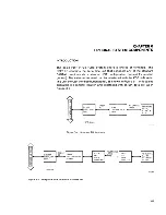
Страница 92: ......

Страница 93: ...erfaced with the KDF 11 8 serial line unit through the distribution panel as shown in Figure 6 1 or it can be operated in a remote location and interfaced with an EIA data set as in Figure 6 2 Vl I ED...

Страница 94: ...s with detachable keyboards They use a nonvolatile memory that remembers the features selected during a setup mode The features that can be set up include tab stops margins characters per line 80 or 1...

Страница 95: ...I standard commands using escape se quences Horizontal tabs Easy interfacing with 20 mA current loop or RS232C levels Keystroke click for rhythmic typing may be disabled Three key rollover protection...

Страница 96: ...ume and keystroke click The communication features are baud rate answerback buffer control keyboard and character set auto disconnect local echo auto new line auto line feed modem half duplex secondar...

Страница 97: ...ee Figure 8 1 In addition to the BA 11 SC 120 Vac expander box the BC02D 03 jumper cable terminator assembly is required to connect the existing backplane to the backplane in the expander box A sample...

Страница 98: ......

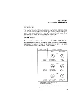
Страница 99: ...e PDP 11 23 PLUS is the power controller Figure 7 1 shows the power connectors used on each model Refer to Table 7 1 for system identification and Table 7 2 for termi nal options according to the type...

Страница 100: ...operation of a system with disk drives Altitude affects the flying height of read write heads in disks and excess humidity and mechanical shock should be avoided The following specifications should be...

Страница 101: ...s and radar transmitters located close to the computer system may affect the performance of the RL02 disk system A magnetic field with an intensity of 50 oersteds or greater might destroy all or some...

Страница 102: ...ether Static Electricity Static electricity may interfere with the system s operation If the system is used in an environment with very low humidity it is advisable to use a humidifier or to place the...

Страница 103: ...uidelines presented in this document PRIORITY CHAINING The position of the module in the computer backplane determines the de vice s priority A signal passes through each module in turn The closer a m...

Страница 104: ...76 Two Backplane Configuration 4_ Both ends of the termination line must be terminated with 120 ohm i e the first backplane must have an impedance of 120 ohms and the last backplane must have a termin...

Страница 105: ...N 93 H9276 1 KDF11 B 2 MSV11 P 3 MSV11 P 4 MSV11 P 5 MSV11 P 6 DZV11 OR DLV11 J 7 DZV11 OR DLV11 J 8 RLV12 9 M9404 00 H9276 10 M9405 00 11 1 12 13 14 OPTIONS 15 I 16 17 18 M9404 00 0 H9276 19 M9405 YA...

Страница 106: ...ction Boot and diagnostic ROM Serial line units Internal external SLU clock jumpers Test jumpers CPU Option Four wire wrap stakes provide user selected features for the central pro cessor unit CPU tha...

Страница 107: ...J IIDAL 07 E114 E102 J23 J24 U oJ22 W2 W1 oc J O o c ro MEMORY MANAGEMENT MMU E74 oJ19 I oJ18 oJ17 OJ16 oJ15 OJ14 oJ13 OJ12 oJ11 oJ10 T DIAGNOSTIC DISPLAY Figure 8 3 KDF 11 8 Jumper Switch and Diagnos...

Страница 108: ...e the following Device Addresses Interrupt Vectors RCSR 777560 Receiver 060 RBUF 777562 Transmitter 064 XCSR 777564 XBUF 777566 When grounded this signal disables the second serial line reg isters Whe...

Страница 109: ...sing ROMs or EPROMs Table 8 3 Diagnostic Bootstrap Program Selection COAL Switch Switch Bit Number Position Function 00 Sl l ON Execute CPU diagnostic upon power up or restart 01 Sl 2 ON Execute memor...

Страница 110: ...ble 8 6 ROM EPROM Jumpers Jumper From J24 J22 To J23 J23 1 installed R removed Memory ROM I R S1 6 05 OFF OFF OFF ON ON S1 7 06 OFF ON ON OFF ON Type EPROM R S1 8 Program 07 Selected ON RK05Boot OFF R...

Страница 111: ...gure the character format for the following options One or two stop bits Seven data bits plus parity Eight data bits without parity Odd or even parity Table 8 8 describes the jumper stake functions an...

Страница 112: ...ed J40 OL 1 OOOJ L When OL 1 PARJ Land OL 1 OOOJ L are both grounded odd par ity is selected If only OL 1 PARJ L is grounded even parity is selected J30 Ground Second SLU This wire wrap stake provides...

Страница 113: ...jumpers enable and disable the break halt feature If this feature is enabled the detection of a break condition by the console UART causes the processor to halt and enter the octal debugging tech niqu...

Страница 114: ...UART Test Jumpers Two types of test jumpers are used for tests performed by manufacturing and field service Tables 8 12 and 8 13 describe these test jumpers and their functions MEMORY EXPANSION The KD...

Страница 115: ...driver to the console serial output line J25 J26 Connects the serial line input from the console connector to the console connector serial line output OR removed I installed Configuring the MSVll P Fi...

Страница 116: ...DDRESS jl y I I JUMPERS __J X 0 wo Voro oS ra oN oM L 1 T I rfl 21 23 22 ___ J EJGGGGEJBDD ro r 0 n non 0 r l r l c IcSR ADDRESS JUMPERS 8 LJ U LJ LJ LJ LJ LJ LJ o J D1 E J E J E J E J t J E J 8 G J p...

Страница 117: ...e Find the PSA value This is done by inserting the MSA and FAR val ues into the equation PSA MSA FAR After you do the subtraction locate the PSA value on Table 8 14 Part 2 A specific configuration of...

Страница 118: ...T OUT IN 16 00100000 OUT OUT OUT IN OUT 24 00140000 OUT OUT OUT IN IN 32 00200000 OUT OUT IN OUT OUT 40 00240000 OUT OUT IN OUT IN 48 00300000 OUT OUT IN IN OUT 56 00340000 OUT OUT IN IN IN 64 0040000...

Страница 119: ...tial CSR memory module is assigned the next higher CSR address Each memory module has four CSR jumper pins A B C and D which can be daisy chained to pin E the ground pin The jumpers allow logic to de...

Страница 120: ...OUT OUT 15 17772134 772134 IN IN IN OUT 16 17772136 772136 IN IN IN IN Power All possible power configurations are shown in Figure 8 4 Bus Grant Continuity These jumpers are removed for systems using...

Страница 121: ...Not used Not used F to H in connected to force starting address to 16K F to H out disables force function 3 to 9 in connected on 16K and 64K MOS chip Connected on 16K and 64K MOS chip Connected only o...

Страница 122: ...system cabinet 4 Slide the top RL02 out to extend in front of the cabinet 5 Putt the side panel up and out as shown arrow in Figure 8 6 To replace the panel simply position the side panel so that the...

Страница 123: ...REAR PANEL DOOR FASTENER Figure 8 6 Left and Right Side Panel Removal RULES FOR EXPANSION 111 SIDE PANEL MA 7383...

Страница 124: ......

Страница 125: ...L021 Disk Subsystem Service Manual EP ORL02 SV Microfiche RLV12 Disk Controller User s Guide DLV11 J User s Guide MSV 11 P User s Manual PDP 11 2B Mounting Box Technical Manual LA 120 User s Guide VT1...

Страница 126: ...AC F053 MC Hardcopy AC F055 MC Hardcopy AA 5133B TC Hardcopy For further information on diagnostic software and the medium desired refer to the PDP 11 Diagnostic Software Components Catalogue AV B021...

Страница 127: ...routine Bootstrap A program used to load the instructions of a program into storage Buffer Control A temporary storage memory used to equalize different operating speeds Bus Error Trap A high priorit...

Страница 128: ...hat automatically moves the decimal point Instruction Set A set of vendor supplied operation codes for a particu lar computer Interlace Mode The assignment of successive addresses to physically separa...

Страница 129: ...itor An asterisk that is printed to inform the user that the program is waiting for instructions Quad Module An option for LSI 11 systems that requires four con nectors on the backplane Queue Overflow...

Страница 130: ......

Страница 131: ...isk Cartridge 8 Configuration 94 PDP 11 23 PLUS System 2 62 63 11 23 Subsystem 62 63 94 KDF 11 B Microprocessor 64 65 MSV 11 P Memory 68 71 102 DZV11 70 72 H9276 Backplane 73 75 RLV12 Disk Controller...

Страница 132: ...Cabinet 108 F FAULT Indicator 4 FDX HDX Switch 4 Finding a Diagnostic Program 12 H HALT Switch 2 Help Message 13 14 H403 Input Box 73 H7861 Power Supply 73 H349 Distribution Panel 76 Installation Chec...

Страница 133: ...rive 78 RL02 Front Panel 2 5 Stabilizer Foot 29 System 1 30 Cabling 34 Cooling 90 Cleanliness 89 Heat Dissipation 89 Radiated Emissions 89 Specifications 88 Static Electricity 90 Power 87 Start Up 7 T...

Страница 134: ......

Страница 135: ...sfy the need you think it was intended to satisfy ______________ Does it satisfy your needs __________ Why __________________ o Please send me the current copy of the Technical Documentation Catalog w...

Страница 136: ...LY MAIL FIRST CLASS PERMIT NO 33 MAYNARD MA POSTAGE WILL BE PAID BY ADDRESSEE Digital Equipment Corporation Educational Services Development and Publishing 200 Forest Street MR1 2fT17 Marlboro MA 0175...

Страница 137: ......

Страница 138: ......

Отзывы: