background image

Installation  3-6

3.6

PAPER FEED

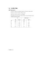
ASF sheet feed:

The sheets are fed into the machine using the ASF  drawer on the machine.

The drawer can hold  120 sheets of 80 g/m

 paper.

Sheets from  60 g/m

to 90 g/m

2   

can be handled.

The printable area for the most common formats  A4 and  Letter/Legal can be
obtained from the table below.

A4

Letter/Legal

mm

inches

mm

inches

M

210

8.26

215.9

8.5

L

203.2

8

203.2

8

S

3.4

0.134

6.4

0.25

D

3.4

0.134

6.4

0.25

T

1

0.04

1

0.04

B

12.7

0.5

12.7

0.5

Содержание DECcolorwriter 520ic

Страница 1: ...DECwriter 500i DECcolorwriter 520ic LJ500 and LJ520 Service Manual EK LJ50E SV A01...

Страница 2: ...uipment Corporation DEC DECcolorwriter 520ic DECwriter 500i and the Digital logo TRADEMARKS CENTRONICS is a registered trademark of Centronics Data Computer Corporation EPSON and LQ 850 are registered...

Страница 3: ...radual approach to printer problems Some paragraphs are marked on a dark background and advise the use of particularly important situations or procedures If these observations are not heeded the print...

Страница 4: ...t the equipment to an outlet of a circuit different from that to which the receiver is connected Consult the dealer or an experienced radio TV technician for assistance Changes or modifications not ex...

Страница 5: ...ite card 256 Kbytes 1 8 2 Times Nordic card 256 Kbytes 1 9 3 Nordic card 256 Kbytes 1 9 1 4 Product OPTIONS 1 9 2 FUNCTIONAL DESCRIPTION 2 1 GENERAL BLOCK DIAGRAM 2 1 2 2 Printer Components and Intern...

Страница 6: ...cket 3 10 3 8 2nd PAPER TRAY ASF2 INSTALLATION 3 11 Paper insertion from second ASF drawer 3 11 3 10 SERIAL INTERFACE INSTALLATION 3 12 3 11 PRINT TEST 3 13 3 12 SYSTEM CONNECTION 3 13 Centronics para...

Страница 7: ...CONDITIONS AND MEANING OPERATIONAL STATUS 6 1 Fault Conditions and Indications 6 2 Normal Conditions and Indications 6 3 7 MECHANICAL ADJUSTMENTS 7 1 PRINT HEAD AND THE WRITING SURFACE GAP 7 1 Proced...

Страница 8: ...9 8 9 7 DISASSEMBLING RE ASSEMBLING THE POWER SUPPLY BOARD 9 9 9 8 DISASSEMBLING RE ASSEMBLING THE PAPER FEED MOTOR 9 11 9 9 DISASSEMBLING RE ASSEMBLING THE CARRIAGE MOTOR 9 12 9 10 DISASSEMBLING RE...

Страница 9: ...manual are applicable to both printer models unless reference is made to a specific model This non impact printer is designed and constructed to guarantee reliability and to give constant quality of...

Страница 10: ...n frequency 3000 Hz Nozzles 51 in 3 vertical groups yellow magenta cyan Vertical construction 2 cols one of 25 and one of 26 nozzles Print head life 200 pages at 8 coverage Print Matrix 300 x 300 dpi...

Страница 11: ...160 color pages Printer Life 5 years Print Path Bi directional Graphic Printing Bit Image Mode density 300 x 300 dpi Ink Save Mode 10 ink saving in graphics mode Linespacing Elementary value 1 300 in...

Страница 12: ...c Compatibility FCC Class B Certified Safety Regulations USA UL 1950 478 Canada CSA C22 2 For mains voltage 220 240 V Electromagnetic Compatibility EN 55022 Class B CEE 87 308 VDE 0871 level B DBP Ver...

Страница 13: ...he optional emulations cannot handle optional fonts on the memory card To enlarge the LQ 850 and 4207 emulation graphic fonts the memory extension memory card must be inserted to handle the DLL functi...

Страница 14: ...adian Further character sets in the machine and available for the ROM resident fonts Courier Letter Gothic and Times Nordic are PC WIN1 ANSI WINDOWS 3 1 CP 852 Latin 2 ISO 8859 2 Latin 2 PC WIN2 East...

Страница 15: ...33 34 TMS Nordic 6 12 Proportional TMS Nordic italic 6 12 Proportional BF Times 7 14 Proportional BF Times italic 7 14 Proportional BF Times 6 12 Proportional BF Times italic 6 12 Proportional BF Time...

Страница 16: ...acter generator but with a different style These fonts are on optional cards and the contents of the card are given below 1 Prestige Elite card 256 Kbytes Style Height Pitch Page format N0 Setup Prest...

Страница 17: ...Nordic italic 8 Proportional Vertical 119 3 Nordic card 256 Kbytes Style Height Pitch Page format N0 Setup Nordic 30 Proportional Vertical 121 Nordic 14 Proportional Vertical 122 Nordic italic 14 Pro...

Страница 18: ......

Страница 19: ...INS SWITCH ASF2 MAINS PARALLEL INTERFACE CENTRONICS SERIAL INTERFACE RS 232 CABLE PAPER PRESENCE PHOTOSENSOR BLACK COLOR SELECTION PHOTOSENSOR CARRIAGE ENCODER PHOTOSENSOR PUSHER SPROCKET MANUAL PAPER...

Страница 20: ...cription 2 2 2 2 Printer Components and Internals The following two figures show the main components and the internals the printer 1 2 12 11 10 9 8 7 6 5 4 3 13 14 15 16 19 17 19 18 19 18 19 Fig 2 1 M...

Страница 21: ...carriage 6 Print head selection lever 7 Operator Panel 8 Paper output tray 9 Paper input tray 10 ON OFF switch 11 Ink tube 12 Ink slide Rear view 13 Manual Feed paper insertion slot cover 14 Power ca...

Страница 22: ...ternal Functional Groups 1 Print Head 2 Paper movement step motor 3 ASF 2 connector 4 Parallel interface connector 5 Main Board 6 Carriage transport DC motor 7 PCMCIA card optional connector 8 Black C...

Страница 23: ...structure as illustrated in figure 2 3 The ink contained in a sponge cartridge is connected to the nozzles via channels in the resin layer of the head This layer is electrically insulated from the mi...

Страница 24: ...y expands and compresses the remaining liquid inside the nozzle A part of the ink bubble is ejected out via the nozzle hole at a speed of approximately 15m s Figure 2 4a e illustrate the prominent bub...

Страница 25: ...NITIAL STATUS Fig 2 4b THE RESISTOR HEATS UP AND STARTS TO FORM VAPOR BUBBLE THE INK EXITS FROM THE NOZZLE Fig 2 4c THE BUBBLE REACHES ITS MAXIMUM DIMENSION Fig 2 4d THE BUBBLE BREAKS DOWN AND AN INK...

Страница 26: ...ns each containing 25 nozzles They are placed in sequence on each column as illustrated in figure 2 5 In addition the matrix is made up of A C and B D nozzles with 2 50 and 1 49 extreme print nozzle d...

Страница 27: ...een adjacent resistors nozzles the drive will be carried out in a particular sequence Fig 2 6 Fig 2 6 Resistor drive sequence Each resistor group is controlled by a 18 8 V driver circuit For correct h...

Страница 28: ...et they are obtained from a Nickel and Gold compound called electroformed They have a tapered structure as can be seen in figure 2 7b The ink is in three containers one for each color Inside each of t...

Страница 29: ...ional Description 2 11 Fig 2 7 Color head Fig 2 7a Ink jet Head for Color Inks 50 m 140 150 m Nozzle Fig 2 7b Nozzle Section Resistor Nozzle Pad Flexible Electric grid Ink filter Ink Cartridge Ink Spo...

Страница 30: ...print nozzles 1 51 are placed vertically on two columns containing respectively 25 and 26 nozzles and horizontally in three groups one for each color They are placed in sequence on each row of nozzles...

Страница 31: ...jacent resistors the drives are carried out in the sequence illustrated in figure 2 9 Fig 2 9 Resistor drive sequence Each resistor group is controlled by an 18 8 V driver circuit For correct head fun...

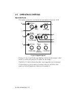
Страница 32: ...Paper Landscape Micro Advance Load Eject Paper Device Fig 2 10 Operator panel The keys A G are used for the paper handling load feed horizontal and vertical format to set the print quality and to repl...

Страница 33: ...head or the ink cartridge LED 2 indicates the replacement request LED 3 warns when there are head change errors Keeping the key pressed at the machine power on activates hexadecimal printing C PORTRA...

Страница 34: ...he sheet is ejected with Sprocket it feeds the continuous module as far as the next first print position TOF If there is no paper in the printer regardless of the operating status in manual paper feed...

Страница 35: ...r on the printer configuration parameters set in the factory will be restored default parameters B INSTALL CARTRIDGE G PAPER MICRO ADVANCE Pressing these two keys simultaneously regardless of the prin...

Страница 36: ...nochrome print matrix protection is exchanged with another of a suitable size for the color head a photosensor is obscured and the electronic board receives the communication to change the machine set...

Страница 37: ...1979 EMI Germany VDE DBP verf 243 1991 standard CEE CEE 87 308 EN 55022 Class B USA FCC FCC part 15 Class B standard Do not connect the printer to common power supply lines or industrial apparatus as...

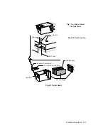
Страница 38: ...g materials for future use should you need to relocate the printer at any time If anything is missing or damaged call your supplier immediately 4 8 5 10 3 2 10 9 1 7 Fig 3 1 Package Contents 1 Printer...

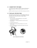
Страница 39: ...cartridge The head has an ink presence sensor that guarantees the constant print quality giving timely indication when the cartridge is finished To install the print head 1 Power up the printer The IN...

Страница 40: ...the machine upper cover 9 Press the INSTALL CARTRIDGE key again the print head will go to its parking position right hand end of stroke and the machine checks the coherence between the installed head...

Страница 41: ...ckage as the memory card Switch the printer off before inserting a card After inserting a memory card with optional emulation only its codes are recognized To reselect the basic emulation PCL3 remove...

Страница 42: ...old 120 sheets of 80 g m2 paper Sheets from 60 g m2 to 90 g m2 can be handled The printable area for the most common formats A4 and Letter Legal can be obtained from the table below A4 Letter Legal mm...

Страница 43: ...side guides 1 according to the width of the sheets US 1 2 3 Fig 3 5 Drawer guides adjustment Insert the drawer into the machine If A5 or Letter size format is used insert the paper stop in the approp...

Страница 44: ...es up to 135 g m2 The printable area for the most commonly used envelope sizes C5 DL C 10 and C6 can be obtained from the table below C5 DL C 10 C6 mm inches mm inches mm inches mm inches M 228 6 9 22...

Страница 45: ...ess to the manual feed slot Fig 3 6 Opening the rear cover With the printer switched on insert the document into the manual feed slot so that it touches the feed rollers Fig 3 8 Manual sheet feed Pres...

Страница 46: ...SF1 ASF2 lit Paper loading by sprocket The sprocket can be used for continuous paper feed or for single sheets The printable area for continuous modules can be obtained from the table below together w...

Страница 47: ...option in the set up parameters Paper insertion from second ASF drawer The ASF2 has a paper feed drawer like the integrated ASF This drawer also has a capacity of 120 sheets of 80 g m2 paper It can ha...

Страница 48: ...connection to the system can be either serial or parallel To make the choice it is only necessary to select the type of interface in the machine set up The figure below shows the 25 pin Cannon connec...

Страница 49: ...ur pages have been printed and the machine is then ready for connection to the system With this test it is possible to verify the machine functioning and to know the printer default set up parameters...

Страница 50: ...ls 19 GROUND 20 GROUND 21 GROUND 22 GROUND 23 GROUND 24 GROUND 25 GROUND 26 GROUND 27 GROUND 28 GROUND 29 GROUND 30 GROUND 31 INIT 32 ERROR 33 LOGIC GROUND 34 NC 35 5 V PULL UP 3 3K ohm 36 INPUT SELEC...

Страница 51: ...nt driver that corresponds to the basic HP DJ 500C emulation For utility programs working in DOS environment the printer set up can be carried out if there is no suitable print driver using a very sim...

Страница 52: ...n the factory Paper Format A4 Paper Device ASF1 Perforation Skip Enabled Text Scale Mode Disabled Always Bidir Disabled Ink Save Mode Enabled BIM Density 75 dpi Line Terminator Normal Print Quality LQ...

Страница 53: ...me with the description for the creation of a parameters configuration file Parameter Description Note PaperFormat A4 A5 Letter Legal US Exec DL COM 10 C5 C6 Tractor PapDev Manual Manual paper feed AS...

Страница 54: ...al print if possible On Always bi directional print InkSaveMode Off Feature disabled On Reduces the ink consumption Bimdensity 75 75 dpi dots per inch 100 100 dpi 150 150 dpi 300 300 dpi Terminator No...

Страница 55: ...ait PS 14 pts 12 BF Times Upright Portrait PS 12 pts 13 BF Times Italic Portrait PS 12 pts 14 BF Times Upright Portrait PS 10 pts 15 BF Times Italic Portrait PS 10 pts 16 BF Times Upright Portrait PS...

Страница 56: ...1 Germany 8 ISO 69 France 9 ISO 15 Italy 10 ISO 60 Norway 1 11 ISO 61 Norway 2 12 ISO 11 Sweden Names 13 ISO 10 Sweden 14 ISO 17 Spain 15 ISO 6US ASCII 16 ISO 2 IRV 17 ISO 16 Portugal 18 ISO 14 JIS AS...

Страница 57: ...P 210 Greece 38 CP 851 Greece 39 ISO 8859 7 Greece 40 PC Win Greek Windows 3 1 41 CP 862 Hebrew 42 ISO 8859 8 Hebrew 43 Slovenia 44 Kamenicky 99 Optional card default set The following symbols are onl...

Страница 58: ...relevant description separate each parameter from its description by a blank a tabulation or an equal sign the last line of the file must be END followed by a return with a line feed To transmit the p...

Страница 59: ...UALLY IF NECESSARY CLEAN USING A RAG DAMPENED WITH ALCOHOL OR A CLEAN BRUSH 4 1 NOZZLE CLEANING AND INK RESET PRIME The external surface of the nozzles is cleaned automatically by the printer during t...

Страница 60: ...operation if the mechanical groups are disconnected from the base If the PRIME slide receives the command with the ink discharge tube disconnected from the blotting pad any object or clothes near it...

Страница 61: ...y out the PRIME command section 4 1 The purpose of this command is to suck some ink through the nozzles to remove any dirt This command should be carried out each time one or more nozzles become clogg...

Страница 62: ...ME operation is not necessary for color heads On termination of the print operation hermetically seal the nozzle area to protect the nozzles from dust and to prevent the ink from drying This operation...

Страница 63: ...haracter fonts available The test supplies the following information type of emulation selected and firmware release on the machine type of print head installed 3600Hz for color head or 5000 Hz for Bl...

Страница 64: ...the ASF drawer with paper preferably A4 Switch off the machine then switch on keeping the ON LINE key pressed during the power on The printer will start to feed the sheets and print the test The firs...

Страница 65: ...nctioning of the print nozzles First the electrical functioning of the nozzles is tested and the result is given by a short line in blue if no faults are found or in red to indicate the presence of fa...

Страница 66: ...Data Scope printout Switch off the printer press the INSTALL CARTRIDGE key and keeping the key pressed switch the printer on again Disabling the Data Scope printout To interrupt the hexadecimal print...

Страница 67: ...sabled Switch the printer off and then on again to check whether the fault persists Next check the power supply board checking the condition of the fuses and that there is power to the main board Fina...

Страница 68: ...with alcohol and if necessary persistent strains faded or damaged vertical bars or dog earred corners replace the part see section 9 11 If the driver voltage is higher than specified 18 8 V the head...

Страница 69: ...erface cable is the correct type and that it is not too long 2 5 meters for the parallel cable Check the connections to the PC and the printer Check that the printer configuration parameters are coher...

Страница 70: ......

Страница 71: ...ch is shown below The LEDs labelled 1 to 8 indicate the machine status end of paper ink or an error message It is mainly these you can use to determine an initial problem Online Ink Paper Supply Color...

Страница 72: ...y the LEDs The operational status of the machine is given in Section 2 LED MEANING 1 2 3 4 5 6 7 8 B B B B B B B B Power on fault B B B Carriage reset fault DB Electronic board fault B Paper fault DB...

Страница 73: ...at ON Horizontal page format OFF ON OFF OFF Print quality LQ OFF OFF ON OFF Print quality NLQ OFF OFF OFF ON Print quality DRAFT ON ON OFF OFF Paper feed Manual ON OFF ON OFF Paper feed ASF1 ON OFF OF...

Страница 74: ......

Страница 75: ...1 3 0 2 0 mm between the head nozzles and the writing surface proceed as follows Loosen the screws that fasten the two plastic supports of the carriage slide bars The left hand support is loosened th...

Страница 76: ...or white stripes along the printing line occur check the belt tension and if necessary correct it Procedure With all parts mounted loosen the motor fixing screws so that the motor is slightly blocked...

Страница 77: ...can be corrected by means of the following procedure Make sure there is paper in the machine Power up the printer keeping the PORTRAIT LANDSCAPE key pressed The machine will automatically print a seri...

Страница 78: ......

Страница 79: ...F2 MPD J9 Memory Card J10 Black Color Head and Paper Presence Photosensors IC1 Paper Motor Driver IC3 8 Bit Buffer IC4 Operational Amplifier IC5 Head Driver IC6 Head Driver IC7 20 V Regulator IC8 Volt...

Страница 80: ...Electrical Interconnections 8 2 8 2 POWER SUPPLY BOARD...

Страница 81: ...Electrical Interconnections 8 3 8 3 POWER SUPPLY CIRCUIT ON MAIN BOARD...

Страница 82: ...D 5 07 25 GND CD 6 08 26 GND CD 7 09 27 GND ACK 0 10 28 GND BUSY0 11 29 GND PE 0 12 30 GND ONLINE0 13 31 INIT 1 AUTOFD0 14 32 ERROR0 15 33 GND GND 16 34 17 35 UART VCC 18 36 SLCTIN INKREF2 1 S50 2 C4...

Страница 83: ...AD6 05 39 AD13 AD7 06 40 AD14 CE1 07 41 AD15 AD10 08 42 CE2 OE 09 43 A11 10 44 A9 11 45 A8 12 46 A17 A13 13 47 P0 A14 14 48 P1 WE 15 49 P2 16 50 P3 VCC 17 51 VCC VPP1 18 52 VPP2 A16 19 53 A15 20 54 A1...

Страница 84: ......

Страница 85: ...free areas before switching the printer off make sure that the head is in the parked position Carriage on the right when disassembling the head do not rest it on the contacts or nozzles side do not to...

Страница 86: ...lack lever on the print head Remove the protective tape from the new ink cartridge Insert the new ink refill immediately pressing it down until it clicks into place Close the cover and press the INSTA...

Страница 87: ...the head together with the ink cartridge To do so grasp the head pulling it towards the rear and remove it from its position If the head is to be reused handle it with care following the instructions...

Страница 88: ...EMBLING RE ASSEMBLING THE CASING Take out the paper drawer Take off the rear cover A carefully remove the paper conveyor B by pushing the side levers gently inward Release the catch C in the center on...

Страница 89: ...n the machine over and release the catches 2 3 4 and 5 Carefully lifting the casing disconnect the console flat cable from its connector 6 on the motherboard and remove the protective strip 7 from the...

Страница 90: ...9 6 9 5 DISASSEMBLING RE ASSEMBLING THE MAIN BOARD Remove the casing section 9 4 Disconnect the head flat cables from connectors 1 and 2 By means of clasps 3 and 4 release the board rack and remove i...

Страница 91: ...ve the protective shield to have access to the board and its components To replace the board remove screws 5 6 7 and 8 9 _______________________Note _________________________ When replacing the mother...

Страница 92: ...rewdriver and unclip it from the printer The button and LED assembly will be loose on the rear of the panel Gently pull off the interconnecting cable to complete the removal ensuring that you mark it...

Страница 93: ...Parts Replacement 9 9 9 7 DISASSEMBLING RE ASSEMBLING THE POWER SUPPLY BOARD Remove the casing section 9 4 Release clasps 1 2 3 4 5 6 and take out the board rack 2 1 3 4 5 6...

Страница 94: ...the board remove screws 8 and 9 _______________________Note _________________________ When replacing the fuse make sure that the new one has the same characteristics When replacing the mother board ch...

Страница 95: ...ut the separator 1 Remove screws 2 and 3 and withdraw the paper feed motor A Free the motor cables from the cable clamp slots and unplug the connector from the mother board _______________________Note...

Страница 96: ...r board section 9 5 Lift tab A and draw out the ground spring 1 Unclasp hook 2 that fastens the bottom then remove the motor from its housing _______________________Note _________________________ When...

Страница 97: ...ION AND SHEET PRESENCE PHOTOSENSORS Remove the mother board section 9 5 Release the sheet presence photosensor 1 from its position and take it out of the machine Release the black color selection phot...

Страница 98: ...and carefully withdraw it from the reading slot on the print head _______________________Note _________________________ When re assembling the strip make sure that it is positioned so that the arrows...

Страница 99: ...the flexible supporting brackets and withdraw the carriage lower guide shaft 2 Draw out the flat cables 3 from the guides on the paper outfeed group and remove the carriage from the machine _________...

Страница 100: ...on 9 4 Withdraw the head flat cable from the guides on the paper outfeed group Free the ends of the ink tube Release the paper outfeed group from clasps 1 2 3 4 and raise it _______________________Not...

Отзывы: