background image

-2-


Installation Guide

(1)

(PL-FD200)


PL-FD200

(1)

Package Contents

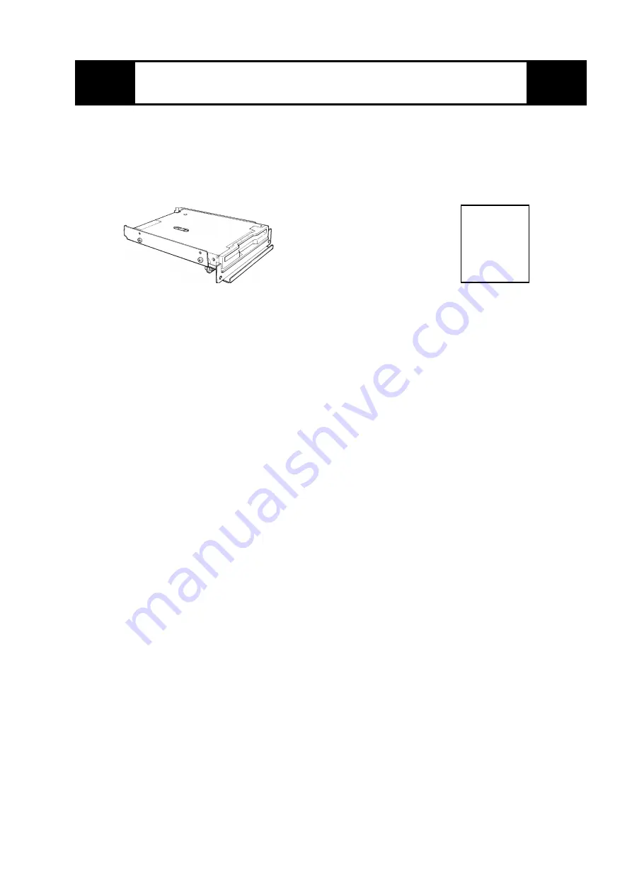
When you open the PL-FD200’s package, please check immediately that
the following items are included.

Installation

Guide

Pro-face has taken the utmost care to insure the quality of this product
when it was shipped. However, should, for any reason, problems or dam-
age have occurred during shipping, please contact your local Pro-face
representative immediately for service.

Содержание PL-FD200

Страница 1: ...se may cause either a breakdown or an electrical shock Do not install or operate this unit in a location where there is direct sunlight excessive heat dust or vibration Do not store or operate this unit near chemicals or where there are chemical fumes Do not use the PL FD200 in locations where corrosive gasses are present To prevent damage to file data be sure to shut down the PL unit s OS before ...

Страница 2: ...mmediately that the following items are included Installation Guide Pro face has taken the utmost care to insure the quality of this product when it was shipped However should for any reason problems or dam age have occurred during shipping please contact your local Pro face representative immediately for service ...

Страница 3: ...Mean Time Between Failures 30 000 hours Ambient Operating Temperature 5 0 C to 50 0 C Ambient Storage Temperature 10 0 C to 60 0 C Ambient Humidity 20 to 80 RH no condensation Shock Resistance During shipping 980 7m s 2 Vibration Resistance During operation 9 8m s 2 10Hz to 25Hz The above specifications are for the PL FD210 unit only Pro face does not guarantee the preservation of any data stored ...

Страница 4: ...nels located on the PL s side face by unscrew ing that panel s two 2 attach ment screws Then remove the blank panel This slot is reserved for the PL FD200 unit Do not insert this unit into any other slot 2 Insert the FDD unit into its installation slot along the inside guide rail until the FDD unit s connector contacts the rear connector receptacle and is inserted securely in place 3 Reattach the ...

Страница 5: ...ts a separate menu area where settings can be entered 4 Use the cursor to select STANDARD CMOS SETUP and the fol lowing screen will appear STANDARD CMOS SETUP BIOS FEATURES SETUP CHIPSET FEATURES SETUP POWER MENAGEMENT SETUP PNP PCI CONFIGURATION LOAD BIOS DEFAULTS LOAD SETUP DEFAULTS SYSTEM MONITOR UTILITY INTEGRATED PERIPHERALS SUPERVISOR PASSWORD USER PASSWORD IDE HDD AUTO DETECTION SAVE EXIT S...

Страница 6: ... hh mm ss 14 50 3 CYLS HEADS PRECOMP LANDZONE SECT0RS MODE Drive C Auto 0b 0 0 0 0 0 AUTO Drive D Auto 0b 0 0 0 0 0 AUTO Drive A 1 44M 3 5 in Video EGA VGA VGA Graphics Mode Normal Halt On All But Keyboard ESC Quit Select Item PU PD Modify F1 Help Shift F2 Change Color Base Memory 640K Extended Memory 31744K Other Memory 384K Total Memory 32768K Note Please be aware that Digital Electronics Corpor...

Отзывы: