background image

5

COBRA-H-DLC       09/2003

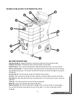
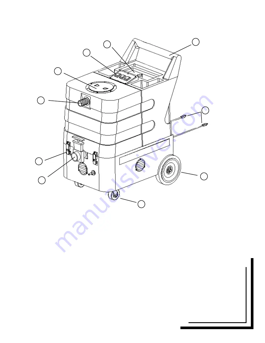
MACHINE DESCRIPTIONS

Operator Handle (1)

 - Operator holds this to move the machine from one location to another.

Solution Tank Lid (2)

 - Fill Solution Tank here with warm water and chemicals.

Switch Plate (3)

 - This is where the switches are located that operate the pump, vacuum and heater.

Recovery Tank Lid (4) 

- The Recovery Tank can be flushed out by running clean water into this opening

with the Drain Gate 

(7)

 open.  The vacuum float Shut-OFF can also be accessed through this opening for

maintenance.

Vacuum Inlet (5)

 - This is where the vacuum hose attaches to the machine.

Latch (6) 

-


Open the latches to access the base compartment, which contains the motors and heater.

Drain Gate (7) 

-


Open this gate to drain the recovered solution out of the machine.  Be sure to keep this

gate clean.

Castor (8) 

-


The castor swivels for easy maneuvering in tight spots.

Wheel (9) 

-


Large, non-marking wheels for ease of transport.

Power Cords (10) 

-


Two, 25 foot cords, rated 12 gauge, 3 wire.  Do not use if either cord is damaged.

The cord with the red sleeve operates the vacuum and the pump.  The other cord operates the heat
exchanger.

1

2

3

4

5

6

7

10

9

8

BECOME FAMILAR WITH YOUR NEW EXTRACTOR

Содержание COBRA-H-DLC

Страница 1: ...1 COBRA H DLC 09 2003 COBRA H DLC OPERATOR S MANUAL ...

Страница 2: ...urs to prevent vacuum motor damage Never use water above 130 F 54 C Do not use outdoors or where temperature is below freezing Protect your machine from any extremes in temperatures Do not let the pump run dry Turn the pump off and refill the tank when cleaning solution gets low Flush the machine with an acid de scaler regularly monthly or more often to prevent a build up of minerals or chemicals ...

Страница 3: ...t outdoors or dropped into water return it to a service center Do not pull by the cord use the cord as a handle close a door on the cord or pull the cord around sharp edges or corners Do not run the machine over the cord Keep the cord away from heated surfaces Do not unplug by pulling on the cord To unplug grasp the plug not the cord Do not handle the plug the cord or the machine with wet hands Do...

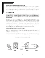
Страница 4: ...and has a grounding plug that looks like the plug illustrated in Figure 1 below Atemporary adapter illustrated in Figures 2 and 3 may be used to connect this plug to a 2 pole receptacle as shown in Figure 2 if a properly grounded outlet is not available The temporary adapter should be used only until a properly grounded outlet Figure 1 can be installed by a qualified electrician The green colored ...

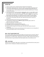
Страница 5: ... this opening for maintenance Vacuum Inlet 5 This is where the vacuum hose attaches to the machine Latch 6 Open the latches to access the base compartment which contains the motors and heater Drain Gate 7 Open this gate to drain the recovered solution out of the machine Be sure to keep this gate clean Castor 8 The castor swivels for easy maneuvering in tight spots Wheel 9 Large non marking wheels ...

Страница 6: ...ch operating temperature 6 Turn the pump on Turn the vacuum on NOTE the pump has a built in pressure switch the pump runs only when you are spraying 7 Begin cleaning using the correct hoses and tool 8 Use defoamer in the recovery tank any time foaming occurs 9 Monitor the water level in the solution tank Do not let the pump run dry 10 When the solution tank gets low turn off the pump fill the solu...

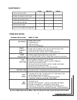
Страница 7: ...mpletely closed or seals are damaged Internal vacuum hose is cracked Recovery tank lid is not closed is cracked or gasket is damaged Recovery tank is warpped or cracked Debris impeding air movement on vac motor impellors No power to motor Test the switch Test the vacuum motor Trying to spray too long Try spraying for 12 15 seconds per cycle Heat exchanger needs to be flushed Wrong tool being used ...

Страница 8: ...8 ...

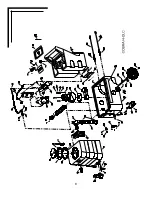
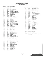
Страница 9: ... Hose Clamp 36 925 Hose pump inlet 3 8 I D 37 138 Bolt 1 4 20 X 1 1 4 38 8 Locknut 1 4 39 2007 Pump 100 psi 40 FP Heat Exchanger complete 41 5 Bolt 1 4 20 X 3 4 42 8 Lock nut 1 4 20 43 455 Bracket heater mount 44 76 Hose Clamp 45 270 Bolt 1 4 20 X 5 46 137 Washer split lock 47 136 Nut finish 1 4 48 14 Washer flat 49 17 Locknut 10 32 50 408B Vacuummotor ITEM PART DESCRIPTION 51 2013 Gasket vacuummo...

Страница 10: ...Wheels Front Castors Heat Exchanger Height Length Width Machine weight One 3 Stage 137 Inches 16 amps each cord Rotationally molded polyethylene 10 Gal 38 L 10 Gal 38 L 100 psi 15 Ft 4 5 m 15 Ft 4 5 m Two 25 ft 7 6 m 12 Gauge 3 wire 8 In 20 3 cm 3 In 7 6 cm 2000 Watt 34 In 86 4 cm 31 In 78 8 cm 17 75 In 45 cm 76 Lb 34 kg COBRA H DLC Lancaster PA 1 800 899 2833 Fax 717 464 5159 www diamondlustre co...

Отзывы: