background image

Содержание HK 36 TC with ROTAX 912 S

Страница 1: ...by Signature Authority Stamp Original date of approval AUSTRO CONTROL GmbH Ab tci lung Flugtcchni k Zcniralc 1 1 030 ViClI Sch lljrchga e 11 26 AP Ze02 This powered sailplane must be operated in comp...

Страница 2: ...rom your powered sailplane Translation of this Airplane Flight Manual has been done by best knowledge and judgement In any case the original document in the German language Doc No 3 01 12 is authorita...

Страница 3: ...page will be indicated by a black vertical line in the left hand margin and the Revision No and the date will be shown on the bottom of the page In the event that you have obtained your HK 36 TC seco...

Страница 4: ...HK 36 TC 100 AFM Diamond AIRCRAFT Introduction Rev Reason Chap Page s Date of Approval Date of Date In Signature No ter Revision Approval serted I Page 0 3 I 09 Jan 2002 Rev 0 1 Doc No 3 01 12 E I L...

Страница 5: ...CG appr 2 16 09 Jan 2002 Ch Page Date 3 1 09 Jan 2002 ACG appr 3 2 09 Jan 2002 ACG appr 3 3 09 Jan 2002 ACG appr 3 4 09 Jan 2002 ACG appr 3 5 09 Jan 2002 ACG appr 3 6 09 Jan 2002 ACG appr 3 7 09 Jan 2...

Страница 6: ...an 2002 6 1 09 Jan 2002 6 2 09 Jan 2002 6 3 09 Jan 2002 6 4 09 Jan 2002 6 5 09 Jan 2002 6 6 09 Jan 2002 6 7 09 Jan 2002 6 6 8 09 Jan 2002 6 9 09 Jan 2002 6 10 09 Jan 2002 6 11 09 Jan 2002 6 12 09 Jan...

Страница 7: ...oved chapter 3 NORMAL PROCEDURES an approved chapter 4 PERFORMANCE a partly approved chapter 5 MASS W EIGHT AND BALANCE a non approved chapter 6 POWERED SAILPLANE AND SYSTEMS DESCRIPTION a non approve...

Страница 8: ...DUCTION 1 2 1 2 CERTIFICATI ON BASIS 1 2 1 3 WARNINGS CAUTIONS AND NOTES 1 3 1 4 EXPLANATIO NS AND ABBREVIATIONS 1 4 1 5 UNITS OF MEASUREMENT 1 6 1 6 DESCRIPTIVE DATA 1 7 1 7 THREE VIEW DRAWINGS 1 8 0...

Страница 9: ...to the current version of the customer s airplane How ever any optional equipment COM NAV etc is not considered For their operation the operation manuals of the respective manufacturers must be follow...

Страница 10: ...of the corresponding procedure leads to an immediate or important degradation in flight safety CAUTION Means that the non observation of the corresponding procedure leads to a minor or to a more or le...

Страница 11: ...titude and temperature b Meteorological terms Pressure altitude Altitude indicated by the altimeter when the subscale is set to 1013 25 hPa or 29 92 inHg c Flight performance Take off roll Distance be...

Страница 12: ...neo us ACL Anti Coll ision Light Strobe Light AGL Above Ground Level CG Center of Gravity ELT Emergency Locator Transmitter GFRP Glass fiber reinforced plastic CFRP Carbo n fiber reinforced plastic AC...

Страница 13: ...ph m s meters per fpm feet per minute m s x 196 85 fpm second Speed of RPM revolutions per minute rotation Mass kg kilograms Ib pounds kg x 2 2046 Ib Force weight N newtons Ibf pounds force N x 0 2248...

Страница 14: ...of the wings In order to enable a fast disassembly and a space saving storage the airplane can be furn ished with a wing fold ing mechanism The power plant is a Rotax R 912 S3 engine with an mt Propel...

Страница 15: ...FM General 1 7 THREE VIEW DRAWINGS Dimensions in millimeters For conversion to inches refer to Section 1 5 I I I I 1 I I I I I I I J I o I I I I I I I I I I I I I 09 Jan 2002 I Page 1 8 I I Doc No 3 0...

Страница 16: ...HK 36 TC 100 AFM General I I I J I I I 1 J I I I I I I I o I t I Page 1 g I 09 Jan 2002 Doc No 3 01 12 E 1 _ _ R _ ev_ _ o I _...

Страница 17: ...2 4 1 ENGINE 2 7 2 4 2 PROPELLER 2 9 2 5 POWER PLANT INSTRUMENT MARKINGS 2 9 2 6 MASS WEIGHT 2 10 2 7 CENTER OF GRAVITY 2 11 2 8 APPROVED MANEUVERS 2 11 2 9 MANEUVERING LOAD FACTORS 2 12 2 10 FLIGHT C...

Страница 18: ...ary for the safe operation of the powered sailplane its engine standard systems and standard equipment The limitations included in this chapter and in Chapter 9 have been approved by Austro Control Gm...

Страница 19: ...speed except speed in smooth air and then only with caution Examples of rough air are lee wave rotors thunderclouds etc VA Maneuvering 176 95 109 Do not make full or abrupt control speed movements ab...

Страница 20: ...thunder clouds whirlwinds and turbulence at close range to moun tain ridges WARNING The maneuvering speed stated on the previous page ap plies to the maximum TIO mass of 770 kg 1698 Ib At lower flight...

Страница 21: ...h a blue radial line At this airspeed the airplane climbs with the maximum possible angle of Best angle of 95 51 59 climb Vx climb speed This airspeed is not marked on the airspeed indicator Recommend...

Страница 22: ...1 1 VS1 at max flight arc mass and most forward CG Upper limit is rough air speed v RA Caution range rough air speed VRA yellow 210 261 113 141 130 162 to never exceed speed VNE arc Maneuvers must be...

Страница 23: ...f the airplane indicates the propeller RPM Consequently all RPM s given in this manual are propeller RPM s in con trast to the engine manual Max TIO power 5 minutes 73 5 kW 1100 DIN hp Max TIO RPM 238...

Страница 24: ...PI classification SF or SG The viscosity should be selected according to the following table Klima Mehrbereichs Ole climatic C O F multi grade oils conditions 40 f lV tropisch 30 trop ical 1 80 Q Q It...

Страница 25: ...PLANT 2 5 POWER PLANT INSTRUMENT MARKINGS Power plant instrument markings and their color code signification are shown below Instrument Red Line Green Arc Yellow Arc Red Line Minimum Normal Caution Ra...

Страница 26: ...ss in baggage compartment 12 kg 26 Ib Maximum useful load including fuel see Mass Balance Form page 6 5 f Maximum useful load on right seat 110 kg 243 Ib Maximum useful load on left seat 110 kg 243 Ib...

Страница 27: ...und in the Airplane Maintenance Manual Doc No 3 02 21 Section 4 The permissible flight CG range is Maximum forward CG 318 mm 12 52 in aft of datum plane Maximum rearward CG 430 mm 16 93 in aft of datu...

Страница 28: ...factors can over stress the airplane 2 10 FLIGHT CREW Solo flights must be cond ucted from the left seat 2 11 KINDS OF OPERATION The powered sailplane is certified for DAY VFR operation Night VFR ope...

Страница 29: ...ime meter 1 Manifold pressure indicator 1 Oil pressure indicator 1 Oil temperature indicator 1 Cylinder head temperature indicator 1 Fuel quant ity indicator 1 Ammeter 1 Fuel pressure warning light NO...

Страница 30: ...Automot ive fuel min RON 95 EN 228 Super EN 228 Super Plus NOTE Due to its high lead concentration AVGAS causes in creased wear of the valve seats and produces more resi due in the combustion chambers...

Страница 31: ...3 amperes Limitations with 30 ampere hours battery No limitations 2 16 LIMITATION PLACARDS Placard Location Remark Maneuvering speed at max gross weight VA 176 km h Min useful load on the seats full...

Страница 32: ...137 6000 19600 210 113 130 Aerobatics and Spin instrument panel are forbidden or LH canopy frame GPS not approved for primary navigation I instrument panel optional Landing Light and Position Lights...

Страница 33: ...GED BAITERY DURING FLIGHT 3 6 3 7 3 PROPELLER REMAINS IN FEATHERED POSITION 3 7 3 7 4 ENGINE FAILURE DURING CRUISE 3 9 3 7 5 CARBURETOR ICING 3 10 3 8 FIRE 3 11 3 8 1 CARBURETOR FIRE 3 11 3 8 2 ELECTR...

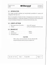
Страница 34: ...s absolutely necessary for the pilot to know the airplane and to have knowledge and experience in solving problems that may occur 3 2 CANOPY JETTISON 1 Red canopy locks LH and RH swing 1800 rearward 2...

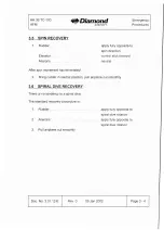
Страница 35: ...havior with power off Excep tion at 50 to 100 power straight and level flight and maximum rearward center of gravity the airplane may perform a stall dive over the left or right wing after entering th...

Страница 36: ...in movement has terminated 2 Bring rudder in neutral position pull airplane out smoothly 3 6 SPIRAL DIVE RECOVERY There is no tendency to a spiral dive The standard recovery procedure is 1 Rudder appl...

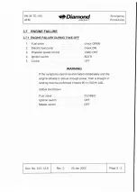
Страница 37: ...ntrol TAKE OFF 4 Ignition switch BOTH 5 Choke OFF WARNING If the symptoms cannot be eliminated immediately and the engine refuses to deliver enough power then a straight in land ing must be performed...

Страница 38: ...TAKE OFF 10 Oil pressure must be available within 10 seconds 11 Choke as required 12 RPM and throttle as requ ired CAUTION After prolonged soaring periods adequate altitude reserve must be ensured fo...

Страница 39: ...tle control in IDLE position 1 Electrical equ ipment OFF 2 Fuel valve OPE N 3 Master switch ON 4 Mode select switch POWER FLIGHT 5 Caution light for coolant level illuminates for approximately 3 secon...

Страница 40: ...wear 12 Oil pressure must be available within 10 seconds 13 Choke as required 14 RPM and throttle as requ ired 15 Electric fuel pump OFF 16 Electrical equipment as required 17 Continue flight norma l...

Страница 41: ...ratures below 10 C 50 O F check BOTH check NOTE If the symptoms cann ot be eliminated and the eng ine re fuses to deliver enough power proceed as fol lows 1 Throttle control IDLE 2 Ignition switch OFF...

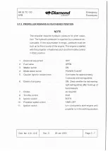
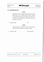
Страница 42: ...or irregular running of the engine without a change in the throttle con trol position the choke position the prope ller setting the airspeed or the altitude 1 Carburetor heat ON NOTE The engine outpu...

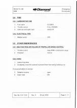
Страница 43: ...1 Master switch OFF 3 9 OTHER EMERGENCIES 3 9 1 MALFUNCTION OR FAILURE OF PROPELLER SPEED CONTROL 1 Throttle control keep RPM in admissible range 2 Airspeed reduce 3 9 2 ICING 1 Leave icing area 2 Co...

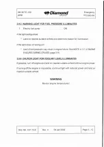
Страница 44: ...guish Lack of fue l pressure may result in engine failure See NOTE in 3 7 4 ENGINE FAILURE DURING CRUISE page 3 9 3 9 4 CAUTION LIGHT FOR COOLANT LEVEL ILLUMINATES If possible turn off eng ine and lan...

Страница 45: ...hen surface again 1 Parachute harness open 2 Seat harness tighten 3 Approach speed normal 4 Touchdown with minimum speed and air brakes retracted NOTE Conditions such as strong headwind danger of wind...

Страница 46: ...MMENDED SPEEDS 4 15 4 5 1 STARTING ENGINE RUN UP TAXIING PROCEDURES 4 1 5 4 5 2 TAKE OFF AND CLIMB 4 19 4 5 3 FLIGHT INCLUDING IN FLIGHT ENGINE STOP START PROCEDURES 4 20 4 5 4 DESCENT 4 23 4 5 5 APPR...

Страница 47: ...bolts are fixed to the fuselage at the wing root The A bolt is placed in front of the spar tunnel and the B bolt lies near the trailing edge Self locking units are screwed onto the B bolts which are a...

Страница 48: ...ip in small circles The aileron and air brake control systems are automatically connected Do not release the wing befo re the main bolt has been inserted completely The wide track of the landing gear...

Страница 49: ...spar tunnel whil e ensuring the smooth insertion of A and B bolts Connect position lights optional and ACL strobe light op tional when the gap between fuse lage and win g is just wide enough to reach...

Страница 50: ...gs ensure that the airplane will not drop onto its nose wheel or tail skid as the center of gravity shifts Winglet installation 1 Clean the bolts and bushes if necessary CAUTION Do not lubricate the b...

Страница 51: ...lly 5 Slip the horizontal stabilizer onto both rearward bolts 6 Screw in the fastening bolt to the stop with an 8 mm hexagon key applying moderate hand torque approximately 6 Nm 4 5 ftlb 7 Check the h...

Страница 52: ...ted prior to the drain check 2 Ensure completeness of the onboard documents and ensure that the remaining operating time before the next scheduled inspection 100 200 or 600 hrs allows for the intended...

Страница 53: ...aileron control system for improper connection lack of load transmis sion and interference Check air brakes for incomplete retraction ensure flushness with the wing surface 8 Inspection of right main...

Страница 54: ...s Check coo lers for obstruction 12 Inspection of left main landing gear Check landing gear strut for damage and cracks Check wheel fairing for damage and looseness Visually check tires and brakes Ens...

Страница 55: ...s and extinguishes CAUTION If the caution light for the coolant level does not extinguish coo lant must replenished dispatcher vessel located cen trally on the engine The upper cowling must be removed...

Страница 56: ...nopy closed locked Fuel valve OPEN Parking brake set Electrical equipment OFF Master switch ON Mode select switch POWER FLIGHT Caution light for coolant level illuminates for approx 3 seconds and exti...

Страница 57: ...engine immediately NOTE When the powered sailplane has been parked for long periods or the hydraulic pressure accumulator is emptied for any other reason a loss of oil pressure may occur after oil pre...

Страница 58: ...sly with the ignition switch the propeller will remain in the take off position Propeller feathering is only possible at 500 RPM or above see Section 7 9 POWE R PLANT Propeller speed control TAKE OFF...

Страница 59: ...visible for both pilots START CHECK 1 Mass Balance checked 2 Main bolts secured 3 Fuel valve OPEN 4 Fuel quantity checked 5 Canopy locked 6 Seat harness on secure 7 Propeller check 8 Magneto check 9 C...

Страница 60: ...brake set 8 Electrical equipment OFF 9 Master switch ON 10 Mode select switch POWER FLIGHT 11 Caution light for coolant level illuminates for approx 3 seconds and extinguishes 12 Propeller speed cont...

Страница 61: ...e powered sailplane has been parked for long periods or the hydraulic pressure accumulator is emptied for any other reason a loss of oil pressure may occur after oil pressure build up in the area of t...

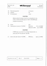
Страница 62: ...with the cowl flap open at 1000 to 1500 RPM also possible during taxiing 25 Choke OFF 26 Check ignition circuits at 1700 RPM RPM drop 50 to 150 RPM difference LH RH max 50 RPM CAUTION If RPM drop is t...

Страница 63: ...rops to approximately 1800 RPM Reset to TAKE OFF position Carry out this procedure at least three times CAUTION Unless this procedure is carried out several times it is not ensured that the pitch chan...

Страница 64: ...km h 49 kts I 56 mph 8 Perform climb with at least 95 km h 51 kts I 59 mph Monitor oil pressure oil temperature and cylinder head temperature which all must stay within the green range at a height of...

Страница 65: ...ight engine stop 1 Throttle control IDLE 2 Electrical equ ipment OFF WARNING Starting the engine with the electric starter can become impossible after prolonged soaring with several electrical consume...

Страница 66: ...l flap CLOSE In flight engine start NOTE Starting the eng ine is possible up to a density alt itude of at least 5000 meters 16400 ft 1 Electrical equipment OFF 2 Master switch ON 3 Mode select switch...

Страница 67: ...to zero for a maximum of 15 seconds 12 Choke push forward as required 13 Electrical equipment as required 14 Oil temperature check 15 Propeller check Throttle contro l adjust 2000 RPM Pull propeller...

Страница 68: ...Cowl flap OPEN 6 Trim as required 7 Air brakes as required NOTE The air brake lever is arrested when the air brakes are extended half way With slightly increased force this posi tion can be overtrave...

Страница 69: ...1 kts 93 mph A control force reversal can occur when the rudder is fully deflected and the ailerons are deflected opposite to the rudder To recover either release the aileron control or apply approxim...

Страница 70: ...main landing gear 11 Wheel brakes apply as required using toe brakes CAUTION The wheels have a differential braking system Apply toe brakes symmetrically to avo id skidding 12 Electric fuel pump OFF I...

Страница 71: ...then retract the air brakes NOTE Climbing is possible with the air brakes fixed in the half extended position 3 Perform climb with at least 95 km h 51 kts 59 mph Monitor oil pressure oil temperature...

Страница 72: ...ch 1 Trim as required 2 Air brakes as required NOTE The air brake lever is arrested when the air brakes are extended half way With slightly increased force this posi tion can be overtraveled in either...

Страница 73: ...TUDE FLIGHT The never exceed speed V NE is reduced at pressure altitudes above 2000 meters 6500 ft as shown in the following table Pressure altitude Never exceed speed VNE meters feet km h kts mph oto...

Страница 74: ...d be avoided because of the reduced visibility CAUTION The airplane has no lightning protection system 4 5 9 AEROBATICS CAUTION Aerobatics and spinning are not permitted 4 5 10 ENGINE SHUT DOWN 1 Prop...

Страница 75: ...g or in unpredictable wind cond itions the airplane should be moored or stored in a hangar It is also advisable to cover the Pitot tube CAUTION Avo id outdoor parking for prolonged periods of time NOT...

Страница 76: ...PEEDS 5 4 5 2 3 TAKE OFF PERFORMANCE 5 5 5 3 ADDITIONAL INFORMATION 5 6 5 3 1 DEMONSTRATED CROSSWIND PERFORMANCE 5 6 5 3 2 GLIDE PERFORMANCE AND FLIGHT POLAR 5 6 5 3 3 TAKE OFF CHARTS 5 7 5 3 4 NOISE...

Страница 77: ...s with the powered sailplane and power plant in good cond ition with the wheel fairings installed and using average piloting techniques The specified airspeeds must be understood as lAS The performanc...

Страница 78: ...h fh v I V V V V V V 1 V V V BO KXJ 120 140 I 160 1 K 200 220 240 260 80 120 140 160 100 180 200 60 70 40 50 80 90 INDICA TED AIRSPEED lAS kts km 140 260 130 240 120 220 110 100 I I I I I I I I I I I...

Страница 79: ...angles in kts IAir brakes Bank angle 3 0 0 1 4 5 0 1 retracted vso 42 kts 45 kts 50 kts 60 kts extended VS1 44 kts 47 kts 52 kts 62 kts Bank angle 3 0 0 4 5 0 retracted vso 48 mph 52 mph 58 mph 69 mph...

Страница 80: ...unway level asphalt surface Take off roll 193 m 633 ft Take off distance to clear 308 m 1010 ft a 15 m 50 ft obstacle NOTE For take off distances under conditions which are different from those descri...

Страница 81: ...at 97 km h 52 kts 60 mph Maximum lift drag ratio 27 at 105 km h 57 kts 65 mph NOTE These figures as well as the graph below are valid for max imum flight mass with winglets wheel fairings and spinner...

Страница 82: ...Take off distance to clear a 15 m 50 ft obstacle Pressure altitude above MSL QFE Head wind OAT Om Oft 400 m 11310 ft 800 m 12620 ft 1200 m 13940 ft comp 0C 1013 hPa 966 hPa 921 hPa 877 hPa kts S1 S2 S...

Страница 83: ...860 614 965 712 1089 823 1240 0 59 623 981 719 1204 837 1257 978 1434 86 728 1112 843 1263 988 1444 1161 1634 32 420 709 482 797 558 902 653 1024 5 59 492 810 571 915 663 1040 778 1188 86 574 922 669...

Страница 84: ...Chapter 6 for Austria only 62 3 dB A for basic training and towing flight Austrian Federal Law Gazette 29 Oct 1993 738th Decree 5 3 5 CLIMB PERFORMANCE Conditions Sea level Full throttle Max flight ma...

Страница 85: ...lane Conditions Pressure altitude 1800 m 5900 ft Prop Manif Fuel flow Cruising speed Endur Range Fuel tank speed press ance capacity lit t US stat US RPM inHg hr gall kmth kts mph h mm km NM miles lit...

Страница 86: ...ces the fuel consumption considerably whilst hard ly affecting the cruising speed For an economical cruise it is recommended to set the propeller speed between 2150 and 2050 RPM and the manifold press...

Страница 87: ...PORT 6 3 6 4 BASIC EMPTY MASS AND MOMENT 6 4 6 5 MASS OF ALL NON LIFTING PARTS 6 4 6 6 MASS AND BALANCE FORM 6 5 6 7 USEFUL LOAD 6 7 6 7 1 MAXIMUM USEFUL LOAD 6 7 6 7 2 USEFUL LOAD ON THE SEATS 6 7 6...

Страница 88: ...3 02 21 Section 4 WARNING Exceeding the maximum flight mass maximum gross weight can lead to overstress ing of the airplane Falling short of the minimum usefu l load on the seats will lead to reduced...

Страница 89: ...Maintenance Log NOTE After equipment changes repair work repainting etc the new empty mass empty weight and the corresponding CG position must be determined by an authorized person in compliance with...

Страница 90: ...um forward position if not more than 220 kg 485 Ib of useful load on the seats and 10 kg 22 Ib of fuel for a half hour flight are aboard 6 5 MASS OF ALL NON LIFTING PARTS The maximum mass weight of al...

Страница 91: ...alance Form must be updated by an authorized person using the data recorded in the currently effective Weighing Report The corresponding instructions can be found in the Airplane Maintenance Manua l P...

Страница 92: ...NCE FORM SERIAL NO _ CALL SIGN _ Minimum useful load Date Empty Empty Max on seats of mass mass useful with full fuel tank A M E weighing weight CG pas load no 12 kg baggage baggage kg mm aft kg kg kg...

Страница 93: ...d on the seats The Mass and Balance Form and the limitations placard in the cockpit show the following data Minimum useful load on the seats for solo flights with a full tank and no bag gage Minimum u...

Страница 94: ...eed 110 kg 243 Ib Lever arm of useful load on the seats A lever arm of 143 mm 5 63 in aft of datum plane is assumed for all CG calculations 6 7 3 USEFUL LOAD IN BAGGAGE COMPARTMENT Maximum useful load...

Страница 95: ...to the Mass and Balance Form It gives the pilot the information whether a loading is permissible taking maximum permissible useful load and minimum useful load on the seats into account It shows the p...

Страница 96: ...B Pilot 65 kg 143 Ib solo flight Long range tank full 60 kg I 132 Ib baggage 12 kg 26 Ib total mass of fuel and baggage 72 kg 159 Ib The loading oversteps the maximum rearward CG position The pilot m...

Страница 97: ...Do t e o t R op oo o lllon l _ kg q Ol 0 Ol Ol 72 0 llJ 70 0 60 c 0 50 q 40 IJ 30 0 2 0 III III 10 0 0 0 t Examples 3 1 0 z 55 Fve l Qvantl i y 0 1 0 I 1 1 tn 10 1 0 12 0 20 3 0 2 10 k g 19 0 Ri f t...

Страница 98: ...eo 0 80 0 0 Ie 12 0 20 I 5 Q la z J 2 1 en en Q J 0 rn Q Q J o CD 10 20 30 40 110 7 0 0 80 40 50 z Fuel Quantity 0 r o 0 r o k g I t lb iUu g L 10 20 30 T l kg I r 210 I I 19 0 I 170 A M E A M E 150 1...

Страница 99: ...TY HARNESSES 7 6 7 7 BAGGAGE COMPARTMENT 7 6 7 8 COCKPiT 7 7 7 9 POWER PLANT 7 9 7 10 FUEL SYSTEM 7 14 7 1 1 ELECTRICAL SYSTEM 7 15 7 12 PITOT AND STATIC SYSTEM 7 15 7 13 MISCELLANEOUS EQUIPME NT 7 16...

Страница 100: ...ave oil dampers but must be locked This is performed by pushing the lever to the forward stop overcom ing the resistance occurring after the air brake is retracted The air brake lever catches when the...

Страница 101: ...bles Elevator control forces can be compensated by means of a spring trim system The aileron and air brake control systems are automatically connected when the wing is installed However the ACL strobe...

Страница 102: ...they lock 7 4 AIR BRAKE SYSTEM There is a blue air brake lever on either side panel By pulling the lever rearward the air brakes are unlocked and extended The air brake lever catches when the air brak...

Страница 103: ...le behind the trim lever The parking brake is released when the button is in the inserted position To set the parking brake draw the button to the stop and actuate the bra ke pedals a few times This p...

Страница 104: ...automatic release Therefore these parachutes cannot be used Each seat is prov ided with a four part harness To fasten the harness the end pieces must be inserted into the lock To open the harness turn...

Страница 105: ...PROPELLER SPEED CONTROL FUEL SHUT OFF VALVE Optional equipment is marked with asterisks o o o MASTER SWITCH SWITCHES BREAKERS LIGHTS FUEL PRESSURE WARNiNG LIGHT MODE SELECT SWITCY 1J _ _ _ L TEMPERAT...

Страница 106: ...for the cabin heat is located in the center conso le under the instru ment pane l Button pulled out Cabin heat ON Cabin air The cabin can be aerated through the swivelling nozzles on the side panels T...

Страница 107: ...OWER PLANT Engine Liquid cooled 4 cylinder four stroke engine Rotax 912 S3 Crankshaft speeds in parentheses Displacement 1352 ern 82 5 in3 Max output power 5 min 73 5 kW 100 DIN hp at 2385 RPM 5800 RP...

Страница 108: ...ly rearward carburetor heat ON The carburetor heat is normally OFF lever fully forward Throttle control Large round lever Lever fully forward FULL THROTTLE Propeller speed control Black star shaped le...

Страница 109: ...a tures below 0 C 32 O F partial closing of the cowl flap avoids continuous operation with an oil temperature below 80 C NOTE Continuous operation with oil temperatures below 80 C may lead to increase...

Страница 110: ...mall pitch is achieved by applying hydraulic pressure supplied by the governor A spring moves the propeller to the feathered pitch position Propeller adjustments are made through the propeller speed c...

Страница 111: ...when it is feathered Therefore a propeller brake is not required The propeller governor is flanged to the engine It is driven directly by the engine The propeller control circuit is part of the engin...

Страница 112: ...ly to the float chambers of the two carburetors Fuel shut off valve The fuel shut off valve is located on the left side of the center console near the pilot s feet Tap in flight direction valve OPEN F...

Страница 113: ...io loud speaker is installed in the baggage compartment A backrest mounted connection set for two headsets is optional 7 12 PITOT AND STATIC SYSTEM Static pressure total head and the pressure for the...

Страница 114: ...DS Limitation placards are shown in Section 2 16 LIMITATION PLACARDS 7 14 2 PLACARDS FOR COCKPIT CONTROLS Placard Place Remark I I next to air brake 2 pieces Air Brakes levers Nose Up I INose Down Tri...

Страница 115: ...I Cabin Air I LH and RH air 2 pieces vent I Fuel Valve OPEN I ICLOSED I next to fuel shut placard off valve CLOSED colored red Parking next to parking Brake pull brake button CANOPY JETTISON Pull bot...

Страница 116: ...CL Landing IC shaded areas FueiPr Pump Lights Light are red on instrument placards panel center sect ion Fuel Qty Oil Temp Oil Press instrument CHT panel RH sect ion next to circuit Generator breakers...

Страница 117: ...I NAV I I GPS I instrument I AOF I I MKR I panel RH section optional B next to circu it brea kers NAV GPS I OOR I I OOMR I I Vol I instrument panel center opt ional section I Headset Pilot I I Headset...

Страница 118: ...40 or according to oil filler cap Flight Manual CAUTION oil inspection DO NOT USE AVIATI ON door in upper colored red GRADE ENGINE OIL cowling inside coola nt dis I I Coolant patcher vesse l equalizin...

Страница 119: ...xt to main 2 pieces wheels I 1 8 bar 26 psi I next to nose wheel The placard for the Start Check is shown in Section 4 4 PREFLIGHT INSPECTION Placards for optional equipment are also included in the s...

Страница 120: ...D SAILPLANE HANDLING CARE AND MAINTENANCE Page 8 1 INTRODUCTION 2 8 2 POWERED SAILPLANE INSPECTION PERIODS 2 8 3 POWERED SAILPLANE ALTERATIONS OR REPAIRS 2 8 4 GROUND HANDLING ROAD TRANSPORT 2 8 5 CLE...

Страница 121: ...ctions are scheduled every 100 200 and 600 hours The respective inspection checklists are prescribed in the Airplane Maintenance Manual Doc No 3 02 21 Section 3 8 3 POWERED SAILPLANE ALTERATIONS OR RE...

Страница 122: ...is adv isabl e to remove insects with a wet sponge at the end of every flying day CAUTION Excessive dirt accumulation degrades flight performance Refer to the Airplane Maintenance Manual Paragraph 1 4...

Страница 123: ...HK 36 TC 100 AFM Diamond AIRCRAFT Supplements CHAPTER 9 SUPPLEMENTS Page 9 1 GENERAL 9 2 9 2 LIST OF SUPPLEMENTS 9 3 09 Jan 2002 _ _ _ _ _ __ Pageg 1 I I Doc No 3 01 12 E I Rev 0...

Страница 124: ...ures given in the Supplements must be app lied in addition to the procedures given in the main part of the Airplane Flight Manual All approved supplements are listed in the List of Supplements in this...

Страница 125: ...Suppl Title Rev Date No No YES NO 1 Tow Plane Operation 0 09 Jan 2002 0 0 3 Electrical Power Socket for 0 09 Jan 2002 0 Additional Equipment 0 5 Operation with Winterization Kit 0 09 Jan 2002 0 0 9 O...

Страница 126: ...Signature Authority Stamp Date of approval AUSTROCONTROL GmbH Abtcilung Flugtcchnik Zcntralc 1 1030 Wicn Schnirchgassc 11 1O f1A l 2002 This powered sailplane must be operated in compliance with the...

Страница 127: ...of Approval Date of Date Signature No ter s Revision Approval Inserted 0 9 1 1 approved Banner 9 1 2 by Ing 1 towing in 2002 05 06 Andreas 2002 06 19 Germany 2 9 1 10 Winkler for ACG Increase in all...

Страница 128: ...ACG appr 9 1 10 23 Apr 2003 3 ACG appr 9 1 11 23 Apr 2003 ACG appr 9 1 12 23 Apr 2003 ACG appr 9 1 13 23 Apr 2003 4 ACG appr 9 1 14 23 Apr 2003 ACG appr 9 1 15 23 Apr 2003 ACG appr 9 1 16 23 Apr 2003...

Страница 129: ...1 4 2 OPERATING LIMITATIONS 9 1 6 3 EMERGENCY PROCEDURES 9 1 11 4 NORMAL PROCEDURES 9 1 13 5 PERFORMANCE 9 1 17 6 MASS WEIGHT AND BALANCE 9 1 26 7 POWERED SAILPLANE AND SYSTEMS DESCRIPTION 9 1 27 8 PO...

Страница 130: ...has been approved in compliance with the draft of the LBA airworthiness requirements for tow plane operation dated February 1971 1 4 EXPLANATIONS Sailplane In this Supplement this term is used to deno...

Страница 131: ...II Cl J w en Cl w J w a U l 6 wwoos i I J _ fr rt I I I I I I I I I I I I I I I I I I I I I I m 1 7 w c W J III Cl J w en Cl w J w a W J III Cl J w en Cl ct W J J w a oct a w W z jjj C l J 0 w iE en a...

Страница 132: ...is the greatest The minimum permissible speed for banner towing is 90 km h 49 kts 56 mph Only sailplanes with a design aerotow speed vT of at least 105 km h 57 kts 65 mph may be towed 2 6 MASS WEIGHT...

Страница 133: ...M EQUIPMENT LIST a Additional equipment for tow plane operation 1 Tost towing device E 85 1 Fitting Dwg No 820 2550 00 00 Sheet 2 1 Release mechanism 1 Caution light amber for the tow rope if required...

Страница 134: ...00 daN 674 Ibf green 1 Rear view mirror if required by national regulations or by the sailplane manu facturer 1 Breaking piece on the sailplane see applicable regula tions for required ultimate load B...

Страница 135: ...Tow Rope and Br e a k i ng Piece Only plastic ropes may be used e g polyamide polyester poly propylene etc in accordance with aeronautical standards DIN standards or factory specifications provided t...

Страница 136: ...open class up to 600 kg 1 1323 Ibs were towed without restrictions on the operating limitations However the pilot must verify in each case whether the sailplane can be towed without exceeding the oper...

Страница 137: ...lity is no longer ensured due to an abnormal position of the towed sailplane the tow rope must be released immediately If the towed sailplane is apparently outside of a 60 cone behind the tow plane i...

Страница 138: ...d via the power setting of the tow plane WARNING During towing the air brakes of the tow plane must not be extended 3 11 BANNER CAUGHT ON LANDING GEAR OR BANNER CANNOT BE DROPPED If possible communica...

Страница 139: ...4 5 2 TAKE OFF AND CLIMB a Sailplane Towing CAUTION During the acceleration phase care must be taken to en sure that the sailplane lifts off first and that the minimum towing speed is reached while s...

Страница 140: ...During cruise select power setting as required CAUTION Monitor the engine temperatures 4 5 5 APPROACH AND LANDING Prior to landing drop tow rope or banner Verify successful release check amber caution...

Страница 141: ...he ground opposite to the direction of approach on the depar ture side of the pick up mounting The banner is picked up in flight Take off is performed with the catch rope attached and pulled behind th...

Страница 142: ...to have a marshaller standing in a safe distance to the pick up mounting CAUTION Do not approach too low The conditions for banner pick up are Electric fuel pump ON Cowl flap OPEN Propeller speed con...

Страница 143: ...osswind component Constant headwind component Lift off speed approximately 90 km h 49 kts 56 mph Climb speed approximately 97 km h 52 kts 66 mph 5 PERFORMANCE 5 2 ACG APPROVED OATA 5 2 3 TAKE OFF PERF...

Страница 144: ...th a Iift to drag ratio of less than 25 and in the range above 500 kg 11021b up to 600 kg 13231b with a lift to drag ratio of less than 58 no data is available WARNING Under unfavorable conditions suc...

Страница 145: ...1 373 585 436 671 515 778 0 191 330 221 374 257 426 300 489 5 15 224 379 261 431 304 495 359 572 30 262 435 307 499 360 574 429 668 Head Pressure altitude above MSL ft QFE inHg wind OAT 0 29 9 1310 28...

Страница 146: ...873 30 381 665 445 761 523 877 621 1021 0 225 429 261 488 304 557 357 641 5 15 264 494 309 565 362 649 429 751 30 311 568 364 653 430 755 513 882 Head Pressure altitude above MSL ft QFE inHg wind OAT...

Страница 147: ...50 696 531 808 636 946 774 1123 0 259 434 303 498 358 577 427 673 5 15 308 507 363 585 433 682 523 803 30 366 588 437 686 525 807 641 960 Head Pressure altitude above MSL ft QFE inHg wind OAT 0 29 9 1...

Страница 148: ...43 686 520 787 615 911 734 1066 0 258 433 300 494 351 565 413 652 5 15 305 502 355 573 419 660 498 767 30 358 578 422 665 500 771 601 904 Head Pressure altitude above MSL ft QFE inHg wind OAT 0 29 9 1...

Страница 149: ...ined in the following tables where S1 Take off roll and S2 Take off distance to clear a 15 m 50 ft obstacle I I I I I I I Take off distance sailplane towing Instruction Flight Sailplane max 380 kg 837...

Страница 150: ...comp r F kts S1 S2 S1 S2 S1 S2 S1 S2 ft ft ft ft ft ft ft ft 32 908 1472 1044 1672 1214 1904 1424 2192 0 59 1065 1695 1234 1936 1443 2214 1700 2562 86 1242 1944 1452 2228 1709 2572 2033 3003 32 731 1...

Страница 151: ...meters per second 410 fpm at sea level in Standard Atmosphere conditions The maximum rate of climb with a banner in accordance with 2 15 2 is 3 05 m s 600 fpm at 105 km h 57 kts I 65 mph at sea level...

Страница 152: ...r the operation of the HK 36 TC as a tow plane the permissible empty mass CG range and the permissible CG range during flight remain unchanged The loading restrictions under 2 6 MASS WEIGHT and 2 10 F...

Страница 153: ...ed A caution light if required is installed in the instrument panel It illuminates as long as the tow rope is being held by the towing device 7 14 PLACARDS I INSCRIPTIONS The following additional plac...

Страница 154: ...OWING DEVICE At each 100 hour inspection of the airplane the system must be cleaned lubricated and checked for poor condition and improper operation The towing device must be removed from the airplane...

Страница 155: ...January 9 2002 3 01 12 E This Supplement does not require approval This powered sailplane must be operated in compliance with the information and limitations contained herein Prior to operating the p...

Страница 156: ...M Supplement NO 3 Electrical Power Socket 0 1 RECORD OF REVISIONS Rev Reason Chap Page s Date of Approval Date of Date Signature No ter Revision Approval Inserted 09 Jan 2002 Rev 0 I Doc No 3 01 12 E...

Страница 157: ...ket 0 2 LIST OF EFFECTIVE PAGES Chapter Page Date 9 3 0 09 Jan 2002 9 3 1 09 Jan 2002 0 9 3 2 09 Jan 2002 9 3 3 09 Jan 2002 1 2 9 3 4 09 Jan 2002 3 4 5 6 9 3 5 09 Jan 2002 7 8 9 3 6 09 Jan 2002 09 Jan...

Страница 158: ...OPERATING LIMITATIONS 9 3 4 3 EMERGENCY PROCEDURES 9 3 5 4 NORMAL PROCEDURES 9 3 5 5 PERFORMANCE 9 3 5 6 MASS W EIGHT AND BALANCE 9 3 5 7 POWERED SAILPLANE AND SYSTEMS DESCRIPTION 9 3 6 8 POWERED SAI...

Страница 159: ...German language is authoritative 1 6 DESCRIPTIVE DATA The electrical power socket is intended for the supply of various additional equipment on the ground This equipment must be provided with a cigar...

Страница 160: ...EMERGENCY PROCEDURES no change 4 NORMAL PROCEDURES no change 5 PERFORMANCE no change 6 MASS WEIGHT AND BALANCE 6 9 EQUIPMENT LIST Additional equipment required for the power socket 1 Socket 1 Wire ha...

Страница 161: ...I INSCRIPTIONS The following additional placard is installed when the additional power socket is installed Placard Place Remark Power connector should be used only on ground next to the electrical Ma...

Страница 162: ...pr in the List of Effective Pages are approved by Signature Authority Stamp Date of approval 1 1J v I I This powered sailplane must be operated in compliance with the information and limitations conta...

Страница 163: ...AIRCRAFT Supplement NO 5 Winterization Kit 0 1 RECORD OF REVISIONS Rev Reason Chap Page s Date of Approval Date of Dat e Signature No ter Revision Approval Inserted I Page 9 5 1 1 09 Jan 2002 Rev 0 1...

Страница 164: ...IST OF EFFECTIVE PAGES Chapter Page Date 9 5 0 09 Jan 2002 0 9 5 1 09 Jan 2002 9 5 2 09 Jan 2002 9 5 3 09 Jan 2002 1 9 5 4 09 Jan 2002 2 ACG appr 9 5 5 09 Jan 2002 3 4 5 6 ACG appr 9 5 6 09 Jan 2002 7...

Страница 165: ...4 2 OPERATING LIMITATIONS 9 5 5 3 EMERGENCY PROCEDURES 9 5 6 4 NORMAL PROCEDURES 9 5 6 5 PERFORMANCE 9 5 6 6 MASS W EIGHT AND BALANCE 9 5 6 7 POWERED SAILPLANE AND SYSTEMS DESCRIPTION 9 5 7 8 POWERED...

Страница 166: ...al document in the German language is authoritative 1 6 DESCRIPTIVE DATA The winterization kit consists of a yellow protective metal plate winterization shield which reduces the cross sectional area o...

Страница 167: ...r 1 Camloc for the attachment of the winterization shield 2 15 OTHER LIMITATIONS The winterization shield should only be used when the outside air temperature on the ground is below 15 C 59 OF An exce...

Страница 168: ...e following items Check whether the outside air temperature permits the use of the winterization shield If operation is permissible check for improper mounting or looseness 5 PERFORMANCE No change 6 M...

Страница 169: ...20 C 36 O F compared to operation without winterization shield Due to the increased oil temperature the water condenses out of the oil more easily 8 POWERED SAILPLANE HANDLING CARE AND MAINTENANCE 8 2...

Страница 170: ...appr in the List of Effective Pages are approved by Signature Authority Stamp Date of approval 1O f1AI 2002 This powered sailplane must be operated in compliance with the information and limitations...

Страница 171: ...IRCRAFT Supplement NO 9 Tow Rope Retraction Device 0 1 RECORD OF REVISIONS Rev Reason Chap Page s Date of Approval Date of Date Signature No ter Revision Approval Inserted 09 Jan 2002 Rev 0 I Doc No 3...

Страница 172: ...an 2002 9 9 5 09 Jan 2002 ACG appr 9 9 6 09 Jan 2002 2 ACG appr 9 9 7 09 Jan 2002 ACG appr 9 9 8 09 Jan 2002 3 ACG appr 9 1 9 09 Jan 2002 ACG appr 9 1 10 09 Jan 2002 4 ACG appr 9 1 11 09 Jan 2002 ACG...

Страница 173: ...ERATING LIMITATIONS 9 9 6 3 EMERGENCY PROCEDURES 9 9 9 4 NORMAL PROCEDURES 9 9 11 5 PERFORMANCE 9 9 13 6 MASS WEIGHT AND BALANCE 9 9 13 7 POWERED SAILPLANE AND SYSTEMS DESCRIPTION 9 9 14 8 POWERED SAI...

Страница 174: ...ledge and judgement In any case the original document in the German language is authoritative 1 4 EXPLANATIONS Sailplane In this Supplement this term is used to denote the towed sailplane or the towed...

Страница 175: ...Retraction Device 1 7 TWO VIEW DRAWING z o i 5w J 2 tw I I rnu rn J co E w l l l l C el l z l 0 0 I E w c Doc No 3 01 12 E W J al t o W VI t W J W 0 Rev a W J co C o w l l C t w J J w 0 t 0 l I W W z...

Страница 176: ...al equ ipment for tow plane operation with tow rope retraction device 1 Tow rope winch and mount 1 Tow rope guide tube 1 Cutting mechanism 1 Tow rope at a length of 30 to 50 m 98 to 164 ft made of PVC...

Страница 177: ...rope retraction dev ice and standard towing dev ice at the same time is not permitted i e only one system may be in use at a time while the other one must be secured aga inst possible use 2 15 2 BANN...

Страница 178: ...ce The standard towing coupling must be secured against use by wire Operation with the Release Mechanism The release cable must be connected with the standard towing coupling The ring couple of the to...

Страница 179: ...ne Flight Manual 3 9 OTHER EMERGENCIES 3 9 1 ABNORMAL POSITION OF TOWED SAILPLANE If maneuverability is no longer ensured due to an abnormal position of the towed sailplane the tow rope must be cut im...

Страница 180: ...as may happen in very few cases the rope will be re tracted just up to the knot In such cases land as advised above and undo the knot In order to avoid knots being tied the pilot of the towed sailpla...

Страница 181: ...stop egg for looseness Verify that cutt ing mechanism is connected to release cable Check movement of the cutting knife for interference by app lying a slight pressure by hand Check mouth piece for d...

Страница 182: ...ation of the red warning light inside the rocker switch indicates operation of the winch 2 In the rear view mirror mounted on the left hand wing observe of the retraction of the tow rope When the end...

Страница 183: ...lement NO 1 remains valid 6 MASS WEIGHT AND BALANCE 6 1 INTRODUCTION For the operation of the airplane as a tow plane the airplane must be weighed in order to determine the empty mass weight and the c...

Страница 184: ...p egg is fixed onto the tow rope and removes any tens ile forces from the tow rope winch The release lever for the standard towing device is also used for the actuation of the cutting mechanism Electr...

Страница 185: ...ON PLACARDS Limitation placards are conta ined in this Supplement in Section 2 16 LIMITATIO N PLACARDS 7 14 2 PLACARDS FOR COCKPIT CONTROLS Placard Place Remark in add ition on the I Towing Coupling C...

Страница 186: ...sm Clean tow rope guide tube and check for chafing or abrasion For re assembly of the cutting knife the engraved arrow must point aft Do not overtighten castle nut and secure it with split pin Lubrica...

Страница 187: ...ce The TBO of the tow rope retract ion device is 4 years or 2000 tows whichever comes first After 2000 tows a new tow rope must be installed If the tow rope is in a poor condi tion a new one must be i...

Отзывы: