background image

MODEL BGS-250 GRINDER 

SECTION 3 

GENERAL 


21 

Grinding & Polishing


OPERATING MANUAL

DECEMBER 2008

You must use Diamatic/Blastrac grinding discs for your warranty to 
remain in effect. 


115V 60 Hz 


Choose the tool most appropriate for the surface to be treated.  This will ensure 
optimal work output and wear for the BGS-250.  The tools available are 
described below. 


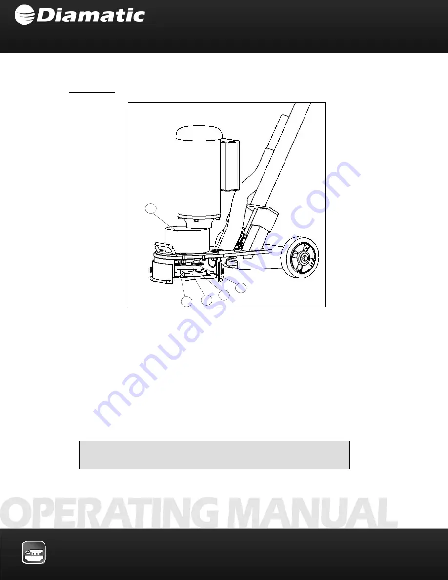
1 Motor 

Adapter 

4 Tooling 

plate 

2 Flex 

Coupling 

5 Gear 

Reducer 

3 Adapter 

Disk 


Figure 3.6.1b 

Содержание BGS-250

Страница 1: ...AFETY INSTRUCTIONS 1 OPERATING MANUAL DECEMBER 2008 Grinding Polishing MODEL BGS 250 Grinder Technical Data 1 Safety Instructions 2 General 3 Transport 4 Initial Operation 5 Operation 6 Maintenance 7 Electrical Systems 8 Fault Diagnosis 9 Spare Parts 10 ...

Страница 2: ...SECTION 1 TECHNICAL DATA 2 OPERATING MANUAL DECEMBER 2008 Grinding Polishing 1 1 Rating 1 2 Unit specifications 1 3 Operative range and correct usage 1 4 Stand by power supply 1 5 Machine type designation CONTENTS SECTION 1 ...

Страница 3: ...n Recommended Dust Collector Contact Diamatic for a suitable dust collector 230V Machines Power consumption 2 2 kW Connected loads 230V 50 Hz for CEE plug Fuse protection 16A Cable Connected loads CEE plug and Coupling 16Amp Up max 50M in 2 5mm2 Diamatic BV Diamatic US Utrechthaven 12 13201 North Santa Fe 3433 PN Nieuwegein Oklahoma City OK 73114 THE NETHERLANDS United States of America T 31 0 30 ...

Страница 4: ...ensions BGS 250 Length 46 4 in 1180 mm Width 20 5 in 520 mm Height 45 3 in 1150 mm Weight 154 lbs 70 kg 1 3 OPERATIVE RANGE AND CORRECT USAGE The BGS 250 is exclusively designed to process horizontal surfaces The machine must not be used for other purposes The manufacturer will not be liable for damage resulting from incorrect usage In these cases the user takes responsibility for all risks ...

Страница 5: ...erator must be operated in accordance with the current U S National Electric Code guidelines or European VDE standards as appropriate this applies but is not limited to the protective earth conductor in particular in order to ensure that all safety devices are functioning and to eliminate possible damage to electrical components 1 5 MACHINE TYPE DESIGNATION BGS 250 Product Type Working width in mm...

Страница 6: ... Personnel selection and qualification 2 4 Safety precautions applicable to different operating conditions 2 5 Special work within the scope of use of the equipment and maintenance activities as well as repairs during operation 2 6 Definition of the safety off position 2 7 General safety considerations 2 8 Electrical engineering regulations CONTENTS SECTION 2 ...

Страница 7: ...ll safety precautions that are to be followed to maximize safety and equipment performance Follow these instructions and take special care in these circumstances In addition to these instructions the general safety precautions and accident prevention guidelines are also to be followed Particular details regarding the economical use of the equipment Information instructions and restrictions with re...

Страница 8: ...o particular working practices for example work organization work procedures and personnel safety Personnel entrusted with working with the machine must read and understand the Operating Instructions before starting work paying specific attention to the Safety information To read these instructions after work has commenced is too late This particularly applies to incidental activities such as sett...

Страница 9: ...stablished and remedied This applies in particular to the fitting and adjustment of safety devices Spare parts must comply with the technical requirements specified by the manufacturer This is always guaranteed if original spare parts are used Intervals for recurring checks and inspections specified in these Operating Instructions must be complied with To perform maintenance work correctly it is i...

Страница 10: ...l safety requirements Personnel who are being trained to operate equipment may only use the machine under constant supervision of an experienced person Do not allow any method of working that impairs safety Recognized official procedures have to be used to ensure the machine is operated in the safest and best conditions Check the machine visually for any damage and defects at least once a day 2 3 ...

Страница 11: ...ne starts up Do not turn off the dust collector while the machine is running Secure the work area around the machine in public areas providing a safety distance of at least 6 5 feet 2 meters from the machine All persons in the proximity of the machine must wear ear protectors and safety shoes In addition the machine operator must wear close fitting protective clothing Use only extension cables use...

Страница 12: ...e and work procedures before starting the cleaning process This includes but is not limited to the following Procedures that are related to normal operation Methods of tools adjustment on the machine and its safety devices All ON and OFF functions that have to be carried out according to the operation manual Methods for maintenance and repair If the equipment is switched off in order to carry out ...

Страница 13: ...ke sure that process materials and replaced parts are disposed of safely and in an environmentally friendly manner Make sure that electrical components used for replacement purposes comply with the original parts and are correctly adjusted if necessary Definition The machine is in a safe condition where it cannot be a hazard Putting the equipment in the Safety off position involves Switching off t...

Страница 14: ...ng From time to time check multi meters to ensure that they are operating correctly 2 7 GENERAL SAFETY CO NSIDERATIONS Any machine if it is not used according to regulations may be hazardous during operation set up and servicing The machine owner is responsible for compliance with the safety regulations during operation and maintenance and for the use of safety devices supplied with the machine as...

Страница 15: ...RAL 15 Grinding Polishing OPERATING MANUAL DECEMBER 2008 3 1 Range of application 3 2 Scope of supply 3 3 Description of the machine 3 4 Operating elements 3 5 Electric components 3 6 The tools 3 7 Care and maintenance CONTENTS SECTION 3 ...

Страница 16: ...manual 1x Using one of the dust collectors specified for your machine ensures nearly dust free operation and also improves the life of the machine and tools Today clean air is important in the workspace Diamatic uses specially designed dust collection systems with a high separation and thus guarantee a high cleaning level Diamatic advises using a recommended Diamatic dust collector This ensures an...

Страница 17: ...R 2008 Figure 3 3 1a 110V 50 Hz 230V 50 Hz 400V 50Hz Machines 1 Height adjusting handle 6 Lifting handle 2 Hand grip 7 Coupling 3 ON OFF Emergency switch 8 Flexible coupling 4 Suction connection piece 9 Adapter 5 Driving motor 10 Cutter plate diamond plate 3 3 DESCRIPTION OF THE MACHINE ...

Страница 18: ...hen on uneven and undulated floors and therefore is also suitable for optimization of surfaces before blasting Alternatively the machine can be used to smooth floor surfaces as a preparation for economical coatings to be applied 1 Height adjusting handle 7 Tool Adapter 2 Hand grip 8 Flexible coupling 3 ON OFF Emergency switch 9 Adapter Disc 4 Suction connection piece 10 Cutter plate diamond plate ...

Страница 19: ...r of revolutions the tool runs at is 1400 rev min U min A special coupling distributes the load which is effective on the tool and ensures a long working life of the machine Hand wheel and mini leveler Before switching on the BGS 250 check that the cutter or diamond plate is in a horizontal position with the mini leveler 4 The adjusting can be done by turning the hand wheel 2 in the right or left ...

Страница 20: ...y when the power supply works properly See to it that the machine is lifted when you switch it on Emergency Stop Switch The emergency stop switch is the red button located on the control box Pressing this switch immediately stops the power supply to all units of the machine This red button is also used as OFF switch 110V 50 Hz 230V 50 Hz 400V 50Hz Models 1 Motor Adapter 3 Adapter Disk 2 Flex Coupl...

Страница 21: ...inding discs for your warranty to remain in effect 115V 60 Hz Choose the tool most appropriate for the surface to be treated This will ensure optimal work output and wear for the BGS 250 The tools available are described below 1 Motor Adapter 4 Tooling plate 2 Flex Coupling 5 Gear Reducer 3 Adapter Disk Figure 3 6 1b 5 3 2 1 4 ...

Страница 22: ...MBER 2008 Figure 3 6 2a 110V 50 Hz 230V 50 Hz 400V 50Hz Models Cutter Plate 50Hz Machines only Remove deposit of dirt Remove cement and glue rests Remove coatings Remove plasticizing Remove carpet and glue rests 1 Motor Adapter 3 Adapter Disc 2 Flex Coupling 4 Tool cutter plate shown ...

Страница 23: ...tion Concrete surfaces general preparation Part No See section10 2 for tooling available Tool Beveled segment diamond plugs Application Concrete surfaces general preparation polishing Part No See section10 2 for tooling available Tool Beveled segment diamond plugs Application Concrete surfaces polishing Part No See section10 2 for tooling available 1 Motor Adapter 4 Tooling plate 2 Coupling 5 Gear...

Страница 24: ...es Generally the Diamatic BGS 250 requires very little attention regarding its maintenance Verify that any wastes or fiber residues do not remain in the area of the grinding disc Never clean the machine using high pressure water jet When the machine is not in use place it on the steering handle This will prevent deformation of the flexible coupling due to a combination of mechanical pressure and h...

Страница 25: ...inding Polishing OPERATING MANUAL DECEMBER 2008 4 1 Unit specifications 4 2 Manual mode of moving the machine 4 3 Transport with cranes or lifts 4 4 Transport of the machine with vehicle 4 5 Operation of the machine while grinding CONTENTS SECTION 4 ...

Страница 26: ... lbs 70 kg To move the machine press down the handgrips 1 see fig 4 3 1 of the machine until the front part rises approximately 4 inches 10 cm from the ground It can now be pushed around on its wheels The machine can only be moved around after attachments are disconnected such as Generator if used Dust collector General accessories 4 1 UNIT SPECIFICATIONS 4 2 MANUAL MODE OF MOVING THE MACHINE ...

Страница 27: ...t verify that the lifting strap s has sufficient capacity to support the weight of the machine the gross weight is shown in Section 4 1 Unit specifications Fasten any lifting slings to the points 2 on the machine frame These points are NOT suitable as a fixing point for fastenings or tie downs during transportation of the machine on a vehicle 4 3 TRANSPORT WITH CRANES OR LIFTS 1 1 2 ...

Страница 28: ...void the machine shifting Secure the machine with a tightening load strap over the lower frame 2 Use at least two straps and tighten down with the load straps to the body of the vehicle The machine must always be operated in accordance with the instructions given in Section 5 2 Initial operation 4 4 TRANSPORT OF THE MACHINE WITH VEHICLE 4 5 OPERATION OF THE MACHINE WHILE GRINDING ...

Страница 29: ...MODEL BGS 250 GRINDER SECTION 5 INITIAL OPERATION 29 Grinding Polishing OPERATING MANUAL DECEMBER 2008 5 1 Preparation for initial operation 5 2 Initial operation CONTENTS SECTION 5 ...

Страница 30: ...and the dust collector with the dust hose Use hose clamps at the connections Make sure the dust bin of the dust collector unit is empty Connect the electric cable of the dust collector with the supply Before start up the operating personnel must be familiar with the safety regulations given in this manual If problems with the BGS 250 arise during the assembly or start up call a qualified person fo...

Страница 31: ...he appropriate European or U S NEC guideline as appropriate Hang the extension cable on the support eye of the machine 2 Verify that the grinding disc is parallel with the floor using the mini leveler Adjust handle if necessary 3 Push the start button 4 5 2 INITIAL OPERATION Figure 5 2 1a 110V 50 Hz 230V 50 Hz 400V 50Hz Pay attention that you always lay down the machine on its steering handle If y...

Страница 32: ...ON 32 Grinding Polishing OPERATING MANUAL DECEMBER 2008 6 1 Operation 6 2 Switching off the machine 6 3 Trouble shooting 6 4 Safety shutdown 6 5 Restarting after a fault 6 6 Proceedings before and after a stationary period CONTENTS SECTION 6 ...

Страница 33: ...ate heat removal Handle all plugs cables hoses and operating elements carefully Avoid contact with live wires Before grinding clean the surface to be treated with a broom There should not be any debris such as stones cloths or standing liquid on the surface Any obstructions in the surface to be treated like concrete reinforcing steel or other objects should be removed from the work surface to prev...

Страница 34: ...ke 2 of the machine you can treat the surface as described You should grind in fan shaped movements Swing the machine at the handgrips 1 and push it during the swing movements forward or pull the machine reverse The working direction should always be away from the dust collector so that neither the dust hose nor the electrical cable could be damaged While using the dust collector observe any speci...

Страница 35: ...in a safe place to secure the machine from unauthorized use If the machine stays at the job site you should cover it with a tarp to protect it from moisture and excessive soiling 6 2 SWITCHING OFF THE MACHINE Figure 6 2 1 Always lay the machine down on the steering handle If you lay the machine down on the grinding disc the flexible coupling could deform due to a combination of mechanical pressure...

Страница 36: ...perating trouble such as vibrations or loud noises switch the machine off immediately by pushing the red OFF button 1 on the power box 6 4 SAFETY SHUTDOWN Before performing inspection or maintenance work make sure that all moving machine parts are stopped Observe the Safety off position Section 2 6 6 5 RESTARTING AFTER A FAULT The results of all electrical repair work must be verified using the ap...

Страница 37: ...equipment as described below Lay down the machine onto the steering handle so that the flexible coupling is not loaded Clean the machine and cover it with a tarp Protect the electric motors from moisture heat dust and shocks Clean the disc and the drive plate area Never do this with high pressure water jets After a long stationary period See Section 5 Initial operation 6 6 PROCEEDINGS BEFORE AND A...

Страница 38: ... OPERATING MANUAL DECEMBER 2008 7 1 Recommendations 7 2 Maintenance and inspection list 7 3 Repairing 7 4 Grinding disc replacement assembly 7 5 Machine maintenance 7 6 The driving motor 7 7 Other maintenance 7 8 Influences on the grinding pattern CONTENTS SECTION 7 ...

Страница 39: ...f working hours is not achieved during the corresponding period the period can be extended However a full overhaul must be carried out at least once a year Due to different working conditions inspection and maintenance intervals may vary Prepare a suitable inspection schedule considering known working conditions and experience Our specialists will be happy to assist with more advice Prior to any r...

Страница 40: ...working correctly Check the power supply cable for damage Check the hose to the dust collector for damage Check whether there is any foreign matter in the coupling of the grinding disc Make sure that the dust bin of the dust collector is emptied Check the grinding disc and the coupling for wear Check the countersunk head screw of the grinding disc for tightness After 203 used discs Check the flexi...

Страница 41: ... personnel get the opportunity to be trained by an expert on the machine If parts or components are to be replaced the following sequence of maintenance must be followed It is advisable to stock all spare or wear parts that cannot be obtained quickly As a rule production standstill periods are more expensive than the cost for carrying the corresponding spare part Screws that have been removed must...

Страница 42: ...sing the handgrips 2 and lay it down on the chassis 3 Remove the grinding disc cutter plate downwards 7 4 GRINDING DISC REPLACEMENT ASSEMBLY Prior to any repair work on the machine and its drives secure the machine against unintentional activation Put the machine in the safety off position See Section 2 6 Figure 7 4 1 Figure 7 4 2 Use of non original replacement components or wear parts may void t...

Страница 43: ...n the centering 3 Set in and tighten the countersunk head screw 4 Remove the block and tilt the machine forward When replacing the grinding disc or at least after the use of 2 3 discs check the condition of the coupling and also of the adapter of the grinding disc Always replace any worn parts Use of non original replacement components or wear parts may void the machine warranty ...

Страница 44: ...g OPERATING MANUAL DECEMBER 2008 Disassembly Step 1 Make sure that the power supply is disconnected from the electrical inlet Remove switch from steering handle Step 2 Remove clip 1 of the spindle and remove bolts 2 7 5 MACHINE MAINTENANCE Figure 7 5 1 Figure 7 5 2 ...

Страница 45: ...ve bolts 1 and move the complete spindle out of the tube Unscrew bolt 2 and remove the hand wheel Remove clamping ring 4 and remove sleeve bearing 6 and shims 5 It s important that no dust gets into the spindle 7 Step 4 Remove cutter plate 50Hz only or grinding disc 1 Unscrew the little bolts 2 inside the dust hood Remove dust hood 3 ...

Страница 46: ... DECEMBER 2008 Figure 7 5 5 Step 5 Now it s possible to take out the wheel bracket 1 Remove star lock ring 2 and remove the wheel and washers 3 Use a new star lock ring when assembling the wheel again Remove felt seal 4 Replace this part with a new one and fix the felt seal with glue ...

Страница 47: ...50Hz Machines Unscrew adapter plate 1 and remove spacer rings 2 Unscrew flexible coupling 3 Remove bolt 4 Remove the coupling 6 with a pulley puller When you do this screw a M10 bolt into the motor shaft This prevents damage to the thread inside the motor shaft Unscrew the nuts 7 to remove the motor Unscrew bolts 10 to remove the lifting handle ...

Страница 48: ...gs 2 Unscrew flexible coupling 3 and remove spacer rings 4 Remove bolt 5 Remove the tooling adapter 6 When you do this screw a 5 16 24 bolt into the gearbox shaft This prevents damage to the thread inside the gearbox shaft Unscrew the nuts 7 to remove the gearbox adapter plate 8 Unscrew bolts 9 to remove the gearbox 10 Unscrew bolts 11 to remove motor 12 4 6 9 5 3 2 1 8 10 12 7 11 ...

Страница 49: ... repaired please contact Diamatic customer service toll free at 800 256 3440 Check the seals for wear and replace them when they no longer provide a good seal against dust emissions from the machine Clean the machine with a damp cloth Based upon the working surface you may have to change the tools grinding disc cutter plate In order to get the best result compare the individual results of the tool...

Страница 50: ...RINDER SECTION 7 MAINTENANCE 50 Grinding Polishing OPERATING MANUAL DECEMBER 2008 ________________________________________________________________ Notes ________________________________________________________________ ...

Страница 51: ... for electrical engineering 8 2 Electric circuit diagram of E00587 1 230V 12 9A 50Hz 8 3 Electric circuit diagram of E01521 230V 12 9A 60Hz 8 4 Electric circuit diagram of E01532 110V 28 0A 50Hz 8 5 Electric circuit diagram of E03951 400V 6 0A 8 6 Electric circuit diagram of P004562 115V 15 0 A 60Hz CONTENTS SECTION 8 ...

Страница 52: ...equipment or operating materials may only be undertaken by a skilled electrician or by trained persons under the guidance and supervision of a skilled electrician as well as in accordance with the electrical engineering regulations The results of all electrical repair work must be verified using the appropriate measurement techniques per the regulations stated in the European VBG4 and VDE 0701 sta...

Страница 53: ...MODEL BGS 250 GRINDER SECTION 8 ELECTRICAL SYSTEMS 53 Grinding Polishing OPERATING MANUAL DECEMBER 2008 8 2 ELECTRIC CIRCUIT DIAGRAM E00587 1 230V 12 9A 50HZ ...

Страница 54: ...MODEL BGS 250 GRINDER SECTION 8 ELECTRICAL SYSTEMS 54 Grinding Polishing OPERATING MANUAL DECEMBER 2008 ...

Страница 55: ...MODEL BGS 250 GRINDER SECTION 8 ELECTRICAL SYSTEMS 55 Grinding Polishing OPERATING MANUAL DECEMBER 2008 ...

Страница 56: ...MODEL BGS 250 GRINDER SECTION 8 ELECTRICAL SYSTEMS 56 Grinding Polishing OPERATING MANUAL DECEMBER 2008 ...

Страница 57: ...MODEL BGS 250 GRINDER SECTION 8 ELECTRICAL SYSTEMS 57 Grinding Polishing OPERATING MANUAL DECEMBER 2008 ...

Страница 58: ...MODEL BGS 250 GRINDER SECTION 8 ELECTRICAL SYSTEMS 58 Grinding Polishing OPERATING MANUAL DECEMBER 2008 8 3 ELECTRIC CIRCUIT DIAGRAM E01521 230V 12 9A 60HZ ...

Страница 59: ...MODEL BGS 250 GRINDER SECTION 8 ELECTRICAL SYSTEMS 59 Grinding Polishing OPERATING MANUAL DECEMBER 2008 ...

Страница 60: ...MODEL BGS 250 GRINDER SECTION 8 ELECTRICAL SYSTEMS 60 Grinding Polishing OPERATING MANUAL DECEMBER 2008 ...

Страница 61: ...MODEL BGS 250 GRINDER SECTION 8 ELECTRICAL SYSTEMS 61 Grinding Polishing OPERATING MANUAL DECEMBER 2008 8 4 ELECTRIC CIRCUIT DIAGRAM E01532 110V 28 0A 50HZ ...

Страница 62: ...MODEL BGS 250 GRINDER SECTION 8 ELECTRICAL SYSTEMS 62 Grinding Polishing OPERATING MANUAL DECEMBER 2008 ...

Страница 63: ...MODEL BGS 250 GRINDER SECTION 8 ELECTRICAL SYSTEMS 63 Grinding Polishing OPERATING MANUAL DECEMBER 2008 ...

Страница 64: ...MODEL BGS 250 GRINDER SECTION 8 ELECTRICAL SYSTEMS 64 Grinding Polishing OPERATING MANUAL DECEMBER 2008 8 5 ELECTRIC CIRCUIT DIAGRAM E03951 400V 6 0A ...

Страница 65: ...MODEL BGS 250 GRINDER SECTION 8 ELECTRICAL SYSTEMS 65 Grinding Polishing OPERATING MANUAL DECEMBER 2008 ...

Страница 66: ...MODEL BGS 250 GRINDER SECTION 8 ELECTRICAL SYSTEMS 66 Grinding Polishing OPERATING MANUAL DECEMBER 2008 ...

Страница 67: ...MODEL BGS 250 GRINDER SECTION 8 ELECTRICAL SYSTEMS 67 Grinding Polishing OPERATING MANUAL DECEMBER 2008 ...

Страница 68: ...MODEL BGS 250 GRINDER SECTION 8 ELECTRICAL SYSTEMS 68 Grinding Polishing OPERATING MANUAL DECEMBER 2008 ...

Страница 69: ...250 GRINDER SECTION 8 ELECTRICAL SYSTEMS 69 Grinding Polishing OPERATING MANUAL DECEMBER 2008 BGS 250 CONTROL PANEL FOR 120V 60Hz A OKLAHOMA CITY OK 73114 13201 N SANTA FE U S A 8 6 ELECTRIC CIRCUIT DIAGRAM 115V ...

Страница 70: ...NUAL STARTER 2 P003755 1 UNDERVOLTAGE TRIP 3 P003741 1 SURFACE MOUNT ENCLOSURE 4 P003740 1 MUSHROOM HEAD STOP BUTTON TWIST RELEASE 5 5330005 25 12 3 CORD 25 SECTION 6 P003757 5 12 3 CORD 5 SECTION 7 P003739 2 CORD GRIP 8 P000712 1 PLUG 2 POLE W GROUND 120VAC 15 AMP 9 714657 1 STRAIN RELIEF 10 P003756 1 CORD GRIP 11 P000329 1 LINK QUICK CLIP CLOSURE ...

Страница 71: ...Grinding Polishing MODEL BGS 250 GRINDER SECTION 9 FAULT DIAGNOSIS 71 OPERATING MANUAL DECEMBER 2008 9 1 Fault diagnosis grinding machine 9 2 Fault diagnosis electrical system CONTENTS SECTION 9 ...

Страница 72: ...ctive motor bearing Debris deposit on the coupling Change the motor Clean the coupling Reduced or no grinding performance Grinding tools have reached the maximum permissible wear Inappropriate grinding tool for the application Replace the worn parts Replace the grinding tools with appropriate grinding tools for the surface to be treated 9 1 FAULT DIAGNOSIS GRINDING MACHINE Prior to any repair work...

Страница 73: ...se of overload Motor protector switch tripped because of low or under voltage condition Motor defective Reduce additional load or increase extension cord wire size Increase extension cord wire size Have motor checked by a trained professional to confirm 9 2 FAULT DIAGNOSIS ELECTRICAL SYSTEM Work on electrical equipment or operating materials may only be undertaken by a skilled electrician or by tr...

Страница 74: ...MODEL BGS 250 GRINDER SECTION 10 SPARE PARTS 74 Grinding Polishing OPERATING MANUAL JUNE 2007 10 1 Spares Parts List BGS 250 10 2 Tooling BGS 250 CONTENTS SECTION 10 ...

Страница 75: ...Grinding Polishing MODEL BGS 250 GRINDER SECTION 10 SPARE PARTS 75 OPERATING MANUAL DECEMBER 2008 10 1 SPARE PARTS LIST BGS 250 ...

Страница 76: ...lamp adjusting ring 1 4 BE0095 Shim Ø16x22x0 5 2 5 BE0098 Bolt M8x10 2 6 E03754 Spindle sleeve 1 7 E03824 Handle grip 2 8 E03758 Handle bar 1 9 BE0083 M8x30 hex Socket head cap 2 10 E03756 Spindle 1 11 E00587 1 Switch inc Break and cable 1 E01532 Electra kit 110V 50Hz 1 E03951 Electra kit 400V 1 P004562 Electrical control panel and harness 115V 60Hz 1 12 E03753 Handle 1 13 E03757 Sleeve Bearing 1 ...

Страница 77: ...Grinding Polishing MODEL BGS 250 GRINDER SECTION 10 SPARE PARTS 77 OPERATING MANUAL DECEMBER 2008 110V 50 Hz 230V 50 Hz 400V 50Hz ...

Страница 78: ...eft 1 3 E03789 Handle bracket right 1 4 E03775 Lifting handle 1 5 E03751 Base plate 1 6 E03761 Felt seal 1 7 E03752 Drive bracket 1 8 BE0096 Washer M20 4 9 E03603 Wheel 2 10 BE0097 Starlock ring Ø20 with cap 2 11 E03759 Upper dust hood 1 12 E03760 Lower dust hood 1 13 E03784 Washer 1 14 E03762 Coupling 1 15 000118 Flexible coupling 1 16 E03250 Spacer ring 3 17 DG05 Adapter 1 18 BE0020 M6x20 bolt 4...

Страница 79: ...MODEL BGS 250 GRINDER SECTION 10 SPARE PARTS 79 Grinding Polishing OPERATING MANUAL JUNE 2007 115V 60 HZ 1 2 3 4 5 6 7 8 9 10 11 12 13 12 14 15 22 ...

Страница 80: ...ter Plate with handle 1 4 E03751 Base plate 1 5 PG 10071 BSDP Adapter Plate 1 6 E03759 Upper dust hood 1 7 E03760 Lower dust hood 1 8 PG 10063 Tool Adapter 1 9 CP 10061 Flexible Coupling 1 10 DG05 Adapter Disc 1 11 E03752 Drive bracket 1 12 BE0096 Washer M20 4 13 E03603 Wheel 2 14 BE0096 Starlock ring Ø20 2 15 E03563 Mini leveler 1 18 BE0020 M6x20 bolt 4 19 BE0016 M6 washer 4 20 E03826 Nylon washe...

Страница 81: ...ECTION 10 SPARE PARTS 81 Grinding Polishing OPERATING MANUAL JUNE 2007 110V 50 Hz 230V 50 Hz 400V 50Hz ITEM PART NO DESCRIPTION QTY 1 B21065 Bolts for diamond cutter plate 4 2 E01443 NINJA Diamond blade 1 10 2 TOOLING BGS 250 ...

Страница 82: ... 60 Hz PG 10158 Scarifier Head Assembly ITEM PART NO DESCRIPTION QTY 3 PA 10672 Drive Plate 1 4 STS15 1130 4P Cutters 42 5 AT 999 664 Washer 54 6 PA 10673 Shaft Support Block 12 7 PA 10674 Shaft 6 8 5028750 Hexagon head screw 12 9 5037600 Spring lock washer 12 10 800772 Washer 12 11 800770 Hexagon socket countersunk head screw 12 ...

Страница 83: ...G 1020GTP 10 DIA 20SEG TURBO PREMIUM BLADE Beveled Segments and Polishing Pads 3 EACH MACHINE PG 10089 POLISHING PAD ADAPTER DP25 BSD50 DIAMOND PLUG 2 5 BEVELED SEGMENT 50 GRIT DP25 BSD80 DIAMOND PLUG 2 5 BEVELED SEGMENT 80 GRIT DP25 BSD150 DIAMOND PLUG 2 5 BEVELED SEGMENT 150 GRIT DP25 BSD300 DIAMOND PLUG 2 5 BEVELED SEGMENT 300 GRIT DP25 BSD500 DIAMOND PLUG 2 5 BEVELED SEGMENT 500 GRIT BG200982 ...

Отзывы: