

Dialogic
®
DM/IP Boards
Quick Install Card for PCI 100 Base-T
DM/IP481-2T1-PCI-100BT
DM/IP601-2E1-PCI-100BT
Part number 64-0031-02
Copyright © 2001-2007
Dialogic Corporation.
All Rights Reserved.
Before You Begin
Protecting the Board from Damage
Caution! All computer boards are sensitive to
electrostatic discharge (“ESD”). Handle all static-
sensitive boards and components at a static-safe work area,
and observe anti-static precautions at all times.
If you are not familiar with ESD safety precautions, visit
http://www.dialogic.com/support/hwinstall
to learn more.
Unpacking the Board
Unpack the Dialogic
®
DM/IP Board (“board”) according
to the following steps:
1.
Prepare a static-safeguarded work area.
2.
Carefully remove the board from the shipping
carton and anti-static packaging. Handle the
board by the edges and avoid touching the
board’s components.
3.
Lay the board on the static-dissipative work
surface.
Note:
Place boards in static-shielding bags when carrying
boards from station to station.
CAUTION
: Do not remove the board from the anti-static
packaging until you are ready to install it. Observe proper
anti-static precautions at all times.
Configuring the Hardware
Board Identification
The DM3 device driver, part of the system software,
assigns board instance numbers in ascending order
(beginning with 0) as it detects each board in your system.
A board instance number is the board identification
number used by the system software to recognize the
board. Refer to the Dialogic
®
Configuration Manager
(DCM) utility to retrieve the board instance (ID)
number(s) assigned to the board(s) in your system.
NOTE:
If you add a board to the system, the existing
board instance (ID) numbers may change, depending upon
the PCI bus and slot number where the new board is
installed.
The system software does
not
recognize or use the setting
number of the rotary switch (SW1) to determine the board
ID number. However, you
must
set SW1 to a unique
number for each DM3 board in your system so that the
power on self test for the board(s) can complete
successfully.
Use a non-magnetic screwdriver to turn SW1 to one of the
15 board ID settings, 1-9 and A-F.
See the DCM On-Line Help for more details on board
identification.
Installing the Hardware
NOTE
: If you are running in a Windows NT
environment, install the software, install the board(s), and
then run the Dialogic
®
Configuration Manager (DCM) to
configure the system.
1.
With your computer on the static-safe work area,
switch off the power and disconnect all power cords
from the electrical outlets.
2.
Remove the cover, select an empty expansion bus
slot, and remove the slot’s retaining screw and
access cover plate.
3.
Use the slot’s board guides as you insert the board
edge connector into the slot. Press firmly until the
board is securely seated in the slot. If you are not
installing your board in an ISA form factor PCI slot,
remove the ISA edge retainer.
4.
Replace and tighten the retaining screw to secure the
board.
5.
Select a new slot and repeat steps 3 and 4 for each
board you are installing.
6.
Use the CT Bus cable to connect the board you are
installing to other boards in the system.
NOTE:
Your system may include both CT Bus boards
and SCbus boards. To connect both board types, you
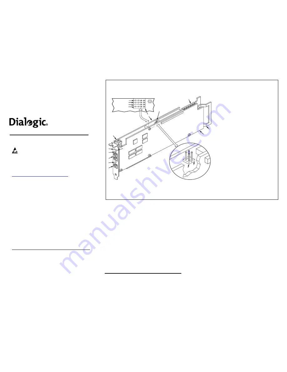
Physical Description
3
1
7
12
11
10
4
5
6
1
2
8
9
Red
Yellow
Green
Loopback
4 3 2 1
*Channels:
JP2B
JP2A
2
1.
Ethernet Interface Connector
2.
Good Link LED
3.
RJ-48C jacks:
Connectors (4) to external
digital telephone network interface.
4.
General Network Interface Alarm LED
5.
Power LED
6.
Reset LED
7.
SW1:
Rotary switch to set board
identification (UNIX systems only).
8.
Alarm LEDs:
Indicate network alarms for
each trunk.
Red:
Alarm to indicate loss of signal.
Yellow:
Alarm to indicate loss of frame
synchronization at far end of external
network.
Green:
Indicates signal present; powered up
and receiving signal from external sources.
Loopback:
Indicates loopback mode is
activated.
9.
CT/MVIP Bus Termination Jumpers*:
Bus signal is terminated when the
corresponding
jumper is installed.
JP2A:
CT Bus termination jumper
JP2B:
MVIP Bus termination jumper
10.
P3:
CT Bus connector
11.
ISA Edge Retainer
12.
Signal Processing Daughterboard
*Note
: Signal must be terminated only on
boards at each end of the CT Bus cable.


