F
G
14
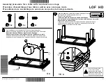
Step 7
The following instructions will illustrate how
to assemble the Trundle from
STEP 7
to
STEP 11
. Please use the Trundle Hardware
Pack:
4360029 (Black)
: T5585196-02
4360129 (White): T5585096-02.
Attach
N
1
X 2 to one
E
with
and
.
N
1
E
E
E
N
1
N
1
N
1
1
3
The Lever "OFF" should
be oriented on the same
side of slat slots.
X 2
X 2
3
1
Содержание 4360029
Страница 9: ...9 Step 2 Attach G to F1 and F2 with and X 2 2 X 2 6 G F1 F2 G G F2 F2 6 2...
Страница 10: ...10 Step 3 Attach J X 2 to A B F1 and F2 with and X 4 X 4 1 5 J 5 A F2 1 F2 F1 B B A A J J...
Страница 12: ...12 Step 5 Insert P into J X 2 as illustrated then lock P into place with Y Y P P P J J J Y J J P...
Страница 15: ...15 Step 8 N N 1 3 E E E N N Attach N X 2 to the other E with and 3 1 X 2 X 2...
Страница 16: ...16 Step 9 M M M E E E Attach M X 2 to E X 2 with X 8 2...
Страница 17: ...17 Step 10 Y E E E E E O Insert O into E X 2 as illustrated then lock O into place with Y Y O O O...


