Doc.: STAL100TX-UM-ENG Rev.: 1.20
STAL1000
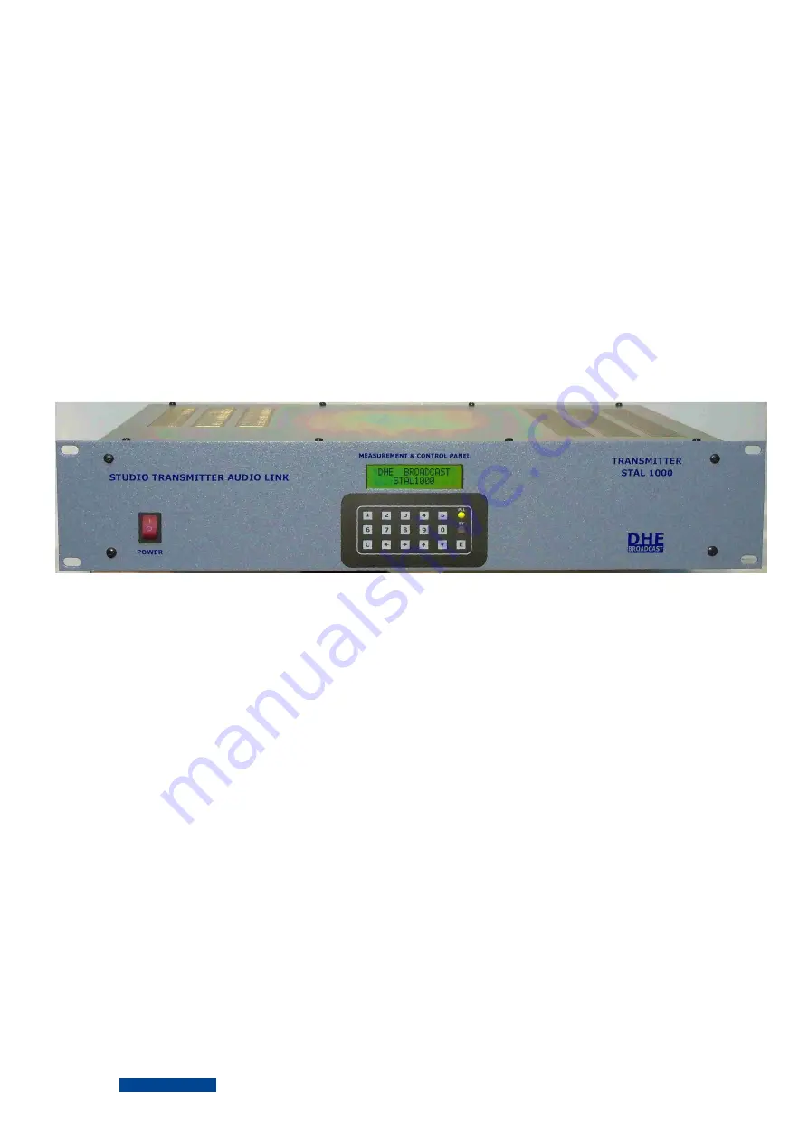
AM/FM STUDIO TO TRANSMITTER AUDIO LINK
TRANSMITTER
USER´s MANUAL
ENGLISH VERSION R1.20
www.dhesystems.com
H
D
E
SYSTEMS
Страница 1: ...Doc STAL100TX UM ENG Rev 1 20 STAL1000 AM FM STUDIO TO TRANSMITTER AUDIO LINK TRANSMITTER USER s MANUAL ENGLISH VERSION R1 20 www dhesystems com H D E SYSTEMS...
Страница 2: ...R STAL1000 Doc STAL1000TX UMI ENG Rev 1 20 SECTION CONTENS 1 REVISIONS 2 ABOUT THIS MANUAL 3 WARRANTY 4 UNPACKING 5 INSTALATION 6 MAINTENANCE AND SERVICING 7 GENERAL DESCRIPTION 8 TECHNICAL SPECIFICAT...
Страница 3: ...ANUAL REVISIONS RECEIVER STAL1000 Doc STAL1000TX UMR ENG Rev 1 20 SECTION 1 REVISION MODEL SOFTWARE DOC REV REPLACE TO REPLACED BY DATE STAL1000 TX 1 00 1 00 1 20 10 02 13 STAL1000 TX 1 20 1 20 1 00 1...
Страница 4: ...quipment there are currents and voltages dangerous for humans never operates it connected to the mains AC line without the factory coverage removed Never open the equipment remove parts or components...
Страница 5: ...ions for which was designed intervention of technical personnel not expressly authorized by DHE SYSTEMS and or not qualified enough damage power conditions outside the specifications environmental con...
Страница 6: ...matches the list contained in the document PACKING LIST in the box If damage is observed ask for an inspection of the carrier and immediately contact the dealer or distributor where you made the purc...
Страница 7: ...WITH THE EQUIPMENT NEVER MAKE DIRECT CONNECTIONS FROM THE INTERIOR OF THE EQUIPMENT ANY OF THE PREVIOUS SITUATIONS WILL REVOKE THE FACTORY WARRANTY THIS EQUIPMENT HAS MONO AND MPX INPUTS COUPLED IN C...
Страница 8: ...in such a way that the ROE is within the parameters accepted by it and if possible verify it using other equipment If you do not have this possibility and if you do not know the conditions of the loa...
Страница 9: ...ly must be disconnected from the power supply before proceeding to remove the coverings and shields HANDLING OF THE MODULES The modules in this equipment are mostly provided with connectors so to remo...
Страница 10: ...SECTION 6...
Страница 11: ...ons and input for auxiliary service The input in Mono mode is balanced unbalanced with XLR connector in Mpx mode and for unbalanced auxiliary service with BNC connector The RF power amplifier is of th...
Страница 12: ...NC Input level Mono 10 to 10 dBm 0 25 a 2 5 Vef 75 Khz Mpx 10 to 10 dBm 0 45 a 4 5 Vef 75 Khz Aux 3 5 Vef 7 5 Khz Frequency response Mono 0 2 dB from 30 to 15000 Hz r referred to the standard preenpha...
Страница 13: ...00 TRANSMITTER Doc STAL1000TX CPI ENG Rev 1 20 SECCION CONTENS 9 1 ACCESS FUNCTIONS AND COMMANDS DECRIPTIONS 9 2 USER MODE 9 10 MULTIFUNCTION 9 15 INITIAL SETTINGS 9 21 TRANSMITTER INFO 9 23 USER MODE...
Страница 14: ...KEY FUNCTION E Enter is the first key to be pressed to access the menu and to exit from the previous sub menus C Correct let to correct errors in the character typed Increment and decrement value of...
Страница 15: ...ailable options are E Exit to P1 1 E 1 1 Transmitter enabled disabled E 1 2 Frequency setting E 1 3 Access to memories E 1 4 Input attenuator modulation level E 1 5 Output power setting E 1 0 Help for...
Страница 16: ...pment retains in non volatile memory the last state in which the function was found to activate deactivate the transmitter when switching it off intentionally or accidentally pej before a power cut In...
Страница 17: ...e the frequency press E to return to P2 The first digit shown corresponds to the first digit of the lower limit of the band Enter the frequency in steps of 25 Khz The accepted terminations are 00 25 5...
Страница 18: ...t is returned to P1 If during the process of typing the key is decided to leave the frequency change option press E to return to P2 2 If the password entered is correct the following message is displa...
Страница 19: ...f the lower limit of the band Enter the frequency in steps of 25 Khz The accepted terminations are 00 25 50 75 Khz The digits of the new frequency are checked when entering the one corresponding to th...
Страница 20: ...d analog format in the form of bars Under normal modulation conditions the analog meter moves from the minimum to the maximum of 75 Khz indicated by bar N 13 The first symbol indicates 110 modulation...
Страница 21: ...level value it is returned to P2 To modify the output power press the keys until the desired value is reached Once this one is reached press E When the minum or maximum values are ratched the ERROR th...
Страница 22: ...2 6 User program help Sequence E 1 0 The display shows For 3 seconds then For 3 seconds then returns to P2 Press E to return to P2 SECTION 9 9 1 TRA 2 KEYB FRE 3 MEM FRE 4 MOD 5 PO...
Страница 23: ...E 2 1 Forward and reflected output power E 2 2 Shows the modulation level E 2 3 Main power suply voltage E 2 0 Help of the Multifunction Meter Si al seleccionar una funci n para el medidor esta es in...
Страница 24: ...Forward and Reflected output power Sequence E 2 1 The display shows Forward and reflected values are shown in digital format with 1 w of resolution Press E to return to P3 SECTION 9 11 FWD 10 W REF 1...
Страница 25: ...format in the form of bars Under normal modulation conditions the analog meter moves from the minimum to the maximum of 75 Khz indicated by bar N 13 The first symbol indicates 110 modulation When the...
Страница 26: ...voltage Sequence E 2 3 The display shows For the 15 Watts option For the 50 Watts option The voltage is displayed in digital format with a resolution of 3 digits Press E to return to P3 SECTION 9 13 V...
Страница 27: ...3 4 Multifunction meter help Sequence E 2 0 The display shows Press E to return to P3 SECTION 9 14 1 POT 2 MOD 3 PS...
Страница 28: ...E 3 The display shows The available options are the following E Returns to P1 1 E 3 1 Operation mode E 3 2 Preenpasis E 3 3 User key E 3 4 Display language E 3 0 Initial settings help SECTION 9 15 IN...
Страница 29: ...pressing 1 Multiplex 2 Mono If the selected mode is incorrect the message ERROR is heard The device returns to P4 1 waitnig for a valid value If the new selected mode is correct the following message...
Страница 30: ...want to change the deenohasis press E to return to P4 Enter the new deenphasis valus pressing 1 0 usec 2 25 usec 3 50 usec 4 75 usec If the new deenphasis selected is incorrect the message ERROR is h...
Страница 31: ...and it is returned to P4 If during the process of typing the new key is decided do not change it press E to return to P4 If the key entered is correct the following message is displayed NOTE The equi...
Страница 32: ...red language pressing 1 Spanish 2 English If the new deenphasis selected is incorrect the message ERROR is heard The device returns to P4 5 If it is correct the display shows the following message for...
Страница 33: ...4 5 Initial settings help Sequence E 3 0 The display shows For 2 seconds Press E to return to P4 SECTION 9 20 1 MODE 2 PREE 3 KEY 4 DIS...
Страница 34: ...sents high limit of the frequency band 5 2 Current frequency Sequence E 4 2 The display shows the current frqeuency setter for 3 seconds then returns to P5 Press E to return to P5 5 3 Frequencies stor...
Страница 35: ...nds XXX Represents the serial number Then the message For 3 seconds and then returns to P5 Press E to return to P5 5 6 Equipment information help Sequence E 4 0 The display shows For 3 seconds then Fo...
Страница 36: ...6 USER MODE HELP Sequence E 0 The display shows For 3 seconds then returns to P1 1 Press E to return to P1 1 SECTION 9 23 1 USER 2 INS 3 INITIAL 4 INFO...
Страница 37: ..._ 1 Forward reflected output power 2 Modulation level 3 Main power supply voltage 0 Multifunction Meter help Press E to return to User Mode To exit to the welcome message press E again 3 Inicial Setti...