DFRobot DFR0225 Скачать руководство пользователя страница 3

(/wiki/index.php/File:RomeoV2R3.png)

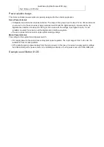
Fig1: Romeo V2 Pin Out

Power solution design

This motor controller power solution is specially designed for the robotics application.
Servo Power terminal

It integrated an external servo power terminal. The range of this power input is about 5~12v. We recommend
you to use 5v. So the servo power supply extension won't break the digital sensors connected to the 3p
digital sensor interface. However,for driving 6~12v servos with the voltage input higher than 5v, it's not
available to extend 5v sensor on all the digital sensor interface anymore.
The servo power terminal won't supply system working voltage.

Motor Power terminal
The setting for the system & motor power switch:

On: supply power to the motor driver and system power regulator. The input range is from 5~23 volts. It's
suitable for most of robot platform.
Off: Isolate the system power supply from the motor power. In this case, it requires to supply system voltage
from Micro USB port,5v power source to 5v & GND pins directly or 5~23v power source to VIN & GND pins.
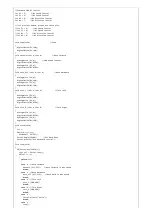
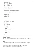
Example use of Button S1­S5

Содержание DFR0225

Страница 1: ...ed by thousands of open source codes and can easily be expanded with Arduino Shields The integrated 2 way DC motor driver and Xbee socket allows you to start your project immediatly without the need f...

Страница 2: ...sensing switching external power input Support Male and Female Pin Header Built in Xbee socket Integrated sockets for APC220 RF Module and DF Bluetooth Module Three I2C TWI Interface Pin Sets two 90...

Страница 3: ...ng 6 12v servos with the voltage input higher than 5v it s not available to extend 5v sensor on all the digital sensor interface anymore The servo power terminal won t supply system working voltage Mo...

Страница 4: ...y if keypress is detected delay 50 wait for debounce time adc_key_in analogRead 0 read the value from the sensor key get_key adc_key_in convert into key press if key oldkey oldkey key if key 0 Serial...

Страница 5: ...ng Fig4 PWM Motor Control Pin Allocation The PWM DC motor control is implemented by manipulating two digital IO pins and two PWM pins As illustrated in the diagram above Figure 5 Pin 4 7 7 8 for old R...

Страница 6: ...1 a digitalWrite M1 LOW analogWrite E2 b digitalWrite M2 LOW void turn_L char a char b Turn Left analogWrite E1 a digitalWrite M1 LOW analogWrite E2 b digitalWrite M2 HIGH void turn_R char a char b Tu...

Страница 7: ...top PLL Control Mode The Romeo also supports PLLPhase locked loop wiki index php Phase_locked_loop control mode wiki index php File Romeov11xxx png Fig5 PLL Motor Control Pin Allocation Configuration...

Страница 8: ...e E2 HIGH analogWrite M2 m2p void setup void int i for i 6 i 9 i pinMode i OUTPUT Serial begin 19200 Set Baud Rate void loop void if Serial available char val Serial read if val 1 switch val case w Mo...

Страница 9: ...Controllers wiki index php Category Motor_Controllers MicroControllers wiki index php Category MicroControllers This page was last modified on 14 March 2016 at 04 15 Content is available under GNU Fr...

Отзывы: