background image

9

Chapter 2


HARDWARE INSTALLATION

User's Manual | 

SO630

1

1

2

8

7

1

1

1

1

1

EPYC

AMD

TM

1

2

12

1

10

11

20

1

1

2

13

14

1

• 

Eight RDIMM/UDIMM up to 256GB


X

System Memory

Features

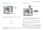
The system board supports the following memory interface.

Single Channel (SC)

Data will be accessed in chunks of 64 bits from the memory channels. DIMMs are on the same 

channel. DIMMs in a channel can be identical or completely different. However, we highly rec-

ommend using identical DIMMs. Not all slots need to be populated.

DDR4_5

DDR4_7

DDR4_6

Before installing the memory module, please make sure that the following safety cautions are 

well-attended.

1.   Make sure the PC and all other peripheral devices connected to it has been powered 

down.

2.   Disconnect all power cords and cables.

3.   Locate the DIMM socket on the system board

4.   Make sure the notch on memory card is aligned to the key on the socket.


X

System Memory

Installing the DIMM Module

Socket Side View

Socket Top View

Memory Module

Notch

Key

Eject Tab

Eject Tab

DDR4_8

DDR4_1

DDR4_3

DDR4_2

DDR4_4

Important:

CH-A: DIMM 1, 2  CH-B: DIMM 3, 4

CH-C: DIMM 5, 6  CH-D: DIMM 7, 8

While only one DIMM is installed in a channel, it should be installed in even num-

ber DIMM (DIMM 2/4/6/8).

Содержание SO630

Страница 1: ...SO630 A 604 M 2045 ATX Industrial Motherboard User s Manual ver MP_MP_4 1521_15 14 ...

Страница 2: ...FCC and DOC Statement on Class B This equipment has been tested and found to comply with the limits for a Class B digital device pursuant to Part 15 of the FCC rules These limits are designed to provide reason able protection against harmful interference when the equipment is operated in a residential installation This equipment generates uses and can radiate radio frequency energy and if not inst...

Страница 3: ...14 Internal I O Connectors 15 SATA Serial ATA 15 Debug 15 Cooling Fan Connectors 16 Power Connector 16 Chassis Intrusion 17 Front Panel 17 Expansion Slots 18 Installing the M 2 Module 18 Battery 19 Chapter 3 BIOS Setup 20 Overview 20 Main 21 Advanced 21 ACPI Configuration 22 CPU Configuration 23 Video Configuration 23 SATA Configuration 24 USB Configuration 25 PCI Express Configuration 26 Debug Co...

Страница 4: ...alling them in your system unit Static electrical discharge can damage computer components without causing any signs of physical damage You must take extra care in han dling them to ensure against electrostatic build up 1 To prevent electrostatic build up leave the system board in its anti static bag until you are ready to install it 2 Wear an antistatic wrist strap 3 Do all preparation work on a ...

Страница 5: ...act your dealer or sales representative Optional Items TBD The board and accessories in the package may not come similar to the information listed above This may differ in accordance with the sales region or models in which it was sold For more information about the standard package in your region please contact your dealer or sales representative Before Using the System Board When installing the ...

Страница 6: ... x Intel i210AT REAR I O Ethernet 2 x GbE RJ 45 USB 6 x USB 3 1 Gen1 Serial 1 x RS 232 422 485 DB 9 1 x RS 232 DB 9 INTERNAL I O USB 2 x USB 3 1 Gen1 SATA 3 x SATA 3 0 2 x SATA 3 0 support RAID 0 1 WATCHDOG TIMER Output Interval System Reset Programmable via Software from 1 to 255 Seconds SECURITY TPM TPM2 0 opt POWER Type ATX power input Consumption TBD RTC Battery CR2032 Coin Cell OS SUPPORT Win...

Страница 7: ...ture by enhancing the capability of a PCIe x16 Gen 3 at 16GB s bandwidth 8GB s in each direction ACPI STR The system board is designed to meet the ACPI Advanced Configuration and Power Interface specification ACPI has energy saving features that enables PCs to implement Power Manage ment and Plug and Play with operating systems that support OS Direct Power Management ACPI when enabled in the Power...

Страница 8: ...AN USB 3 1 Gen1 4x USB 3 1 Gen1 PCIe x8 PCIe x4 Gen 3 DDR4 R UDIMM 2x Channel A DDR4 R UDIMM 2x Channel B DDR4 R UDIMM 2x Channel C DDR4 R UDIMM 2x Channel D PCIe x8 PCI PCIe x1 M 2 2280 M key PCIe x2 SATA PCIe x2 SATA 3 0 2x PCIe x1 Gen 2 LAN ASM1062R IT8893E Switch PCIe x8 PCIe x16 PCIe x8 PCIe x8 Switch PCIe x8 PCIe x16 PCIe x8 PCIe x8 Switch PCIe x8 USB 3 1 Gen1 4x PCIe x1 uPD720201 ...

Страница 9: ...If such a station is not available you can provide some ESD pro tection by wearing an antistatic wrist strap and attaching it to a metal part of the system chassis If a wrist strap is unavailable establish and maintain contact with the system chassis throughout any procedures requiring ESD protection Note Some components are optional and only available upon request X LED and Switch CPU 1 1 2 8 7 1...

Страница 10: ...R4_5 DDR4_7 DDR4_6 Before installing the memory module please make sure that the following safety cautions are well attended 1 Make sure the PC and all other peripheral devices connected to it has been powered down 2 Disconnect all power cords and cables 3 Locate the DIMM socket on the system board 4 Make sure the notch on memory card is aligned to the key on the socket X System Memory Installing ...

Страница 11: ... while applying and maintaining even pressure on both ends Step 3 The tabs snap automatically to the edges of the card and lock the card in place X System Memory X Installing the DIMM Module Please follow the steps below to remove the memory card from the socket Step 1 Press the eject tabs at both ends of the socket outward and downward to release them from the locked position Step 2 The memory ca...

Страница 12: ...nk as sembly Do not spread the paste all over the surface When you later place the CPU on top of the heat sink the compound will disperse evenly Some heat sinks come with a patch of pre applied thermal paste Do not apply thermal paste if the fan with heat sink already has a patch of thermal paste on its underside Peel the strip that covers the paste before you place the CPU on top of the heat sink...

Страница 13: ...t values stored in the ROM BIOS To load the default values stored in the ROM BIOS please follow the steps below 1 Power off the system and unplug the power cord 2 Put a jumper cap on pin 2 and pin 3 Wait for a few seconds and set it back to its de fault setting i e jumper cap on pin 1 and pin 2 3 Plug the power cord and power on the system 2 3 On Clear CMOS Data 1 2 On Normal default 1 3 2 1 3 2 X...

Страница 14: ...s remote display terminals and other serial devices The two COM ports support RS232 two DB9 connector at the rear side and one internal pin header connector for monitoring the BMC RS232 RS422 RS485 Pin COM1 2 COM1 COM1 1 DCD TXD Data 2 RXD TXD Data 3 TXD RXD 4 DTR RXD 5 GND GND GND 6 DSR 7 RTS 8 CTS 9 RI COM Port Pin Assignment X Rear I O Ports Note The BMC COM port is used to monitor the IPMI and...

Страница 15: ...ternal USB ports may be mounted on a card edge bracket Install the card edge bracket to an available slot at the rear of the system chassis and then insert the USB port cables to a connector Pin Assignment Pin Assignment 1 5V_USB3 11 USB2_1P_C_3 2 USB3_RX1_DN_C_3 12 USB2_1N_C_3 3 USB3_RX1_DP_C_3 13 GND 4 GND 14 USB3_TX2_DP_C_3 5 USB3_TX1_DN_C_3 15 USB3_TX2_DN_C_3 6 USB3_TX1_DP_C_3 16 GND 7 GND 17 ...

Страница 16: ...d to your Serial ATA device SATA 3 P0 and SATA 4 P1 support RAID SATA Serial ATA SATA 0 1 2 from top to bottom 5 Serial ATA 3 0 ports with data transfer rate up to 6Gb s Integrated Advanced Host Controller Interface AHCI controller Support RAID 0 RAID 1 SPAN Features 7 RX GND TX TX GND 1 RX GND SATA 3 P0 4 P1 from top to bottom Debug X Internal I O Connectors 1 1 2 8 7 1 1 1 1 1 EPYC AMD TM 1 2 12...

Страница 17: ...nnector enables the delivery of more 12VDC current to the processor s Voltage Regulator Module VRM The power connectors from the power supply unit are designed to fit the 24 pin and 8 pin con nectors in only one orientation Make sure to find the proper orientation before plugging the connectors The system board requires a minimum of 300 Watt power supply to operate Your system con figuration CPU p...

Страница 18: ...2 GND Chassis Intrusion Pin Assignment HDD LED Hard Disk Drive LED Lighting of the LED indicates that the hard drive is being accessed RESET Reset Switch This switch allows you to reboot without having to power off the system Power Standby LED When the system s power is on this LED will light up When the system is in the S1 POS Power On Suspend state it will blink at 1 second intervals When the sy...

Страница 19: ... modules and make the M 2 more suitable in application for solid state storage PCIe 2 PCIe x8 shared with PCIe 1 PCIe 5 PCIe x16 x8 when PCIe 6 in use PCIe 4 PCIe x8 shared with PCIe 3 PCIe 6 PCIe x8 shared with PCIe 5 PCI M 2 M Key 2280 PCIe x4 NVMe PCIe 3 PCIe x16 x8 when PCIe 4 in use PCIe 1 PCIe x16 x8 when PCIe 2 in use a b c d e f g h Expansion Slots X Internal I O Connectors Installing the ...

Страница 20: ...ectors X Expansion Slots 1 1 2 8 7 1 1 1 1 1 EPYC AMD TM 1 2 12 1 10 11 20 1 1 2 13 14 1 The lithium ion battery addendum supplies power to the real time clock and CMOS memory as an auxiliary source of power when the main power is shut off Insert a coin cell battery into the holder and make sure the polarities are correctly oriented the cap side rimmed rounded edge is negative and should be facing...

Страница 21: ...off In general the information stored in the CMOS RAM of the EEPROM will stay unchanged unless a configuration change has been made such as a hard drive replaced or a device added It is possible that the CMOS battery will fail causing CMOS data loss If this happens you need to install a new CMOS battery and reconfigure the BIOS settings Default Configuration Most of the configuration settings are ...

Страница 22: ...ASE REDUCE Project Name BIOS Version Processor Type CPUID CPU Speed CPU Stepping L1 Cache L2 Cache L3 Cache Number Of Processors Microcode Rev Total Memory System Memory Speed DIMM 1 DIMM 2 DIMM 3 DIMM 4 DIMM 5 DIMM 6 DIMM 7 DIMM 8 System Time System Date Security Advanced Boot Exit Main X Advanced The Advanced menu allows you to configure your system for basic operation Some entries are defaults ...

Страница 23: ...is used to enable or disable to support display logo with ACPI BGRT table Wake On RTC When Enabled the system will automatically wake up from S4 S5 state at a designated time every day via the Real time clock RTC battery Wake up time Configure the time of day the system will wake on RTC HH MM SS This field will only ap pear when Wake On RTC is enabled X Advanced InsydeH2O Setup Utility Rev 5 0 F1 ...

Страница 24: ...rs and the user may experience better computational efficiency of the system Please make sure that the OS operating on your system is optimized for SMT or update to a version supports SMT This field is only available with the CPU supported Video Configuration InsydeH2O Setup Utility Rev 5 0 F1 Help Esc Exit Select Item Select Item F5 F6 Change Values Enter Select SubMenu F9 Setup Defaults F10 Save...

Страница 25: ...TA Port Hot Plug SATA1 SATA Port Hot Plug SATA2 SATA Port Hot Plug M 2 M CN2 SATA Port Hot Plug Enabled Auto Not Installed Enabled Disabled Not Installed Enabled Disabled Not Installed Enabled Disabled Not Installed Enabled Disabled Advanced SATA Controller s Enable or disable the Serial ATA controller This following fields will only be displayed when this field is enabled SATA Speed Select Serial...

Страница 26: ...isable the Serial ATA controller This following fields will only be displayed when this field is enabled Raid OPROM Enable to OPROM for RAID management USB Configuration Legacy USB Support Enabled Enable Legacy USB support Disabled Keep USB devices available only for EFI applications InsydeH2O Setup Utility Rev 5 0 F1 Help Esc Exit Select Item Select Item F5 F6 Change Values Enter Select SubMenu F...

Страница 27: ...is only available for the PCIE1 port This field may not appear when the speed of the port is not configurable Hot Plug Enable or disable hot plug function of the port This field may not appear when the port does not support hot plug InsydeH2O Setup Utility Rev 5 0 F1 Help Esc Exit Select Item Select Item F5 F6 Change Values Enter Select SubMenu F9 Setup Defaults F10 Save and Exit PCI Express Port ...

Страница 28: ... to output debug mes sage from COM port Debug Configuration Dynamic EFI DEBUG This debug function is only used for J1 internal UART EFI debug baud rate On 115200 Advanced X Advanced UEFI Device Manager Configure UEFI device with option ROM such as LAN card etc InsydeH2O Setup Utility Rev 5 0 F1 Help Esc Exit Select Item Select Item F5 F6 Change Values Enter Select SubMenu F9 Setup Defaults F10 Sav...

Страница 29: ...t Mode Counter Case Open Status Case Open Alert Clean Case Open Status Hardware Monitor Advanced Enable 228 IRQ4 RS232 Enable 338 IRQ3 Enable Second 38 Close Enable COM1 Enables or disables the serial ports COM The following bracketed fields will only appear when the port is enabled COM2 Enables or disables the serial ports COM The following bracketed fields will only appear when the port is enabl...

Страница 30: ...rs the same index as the Boundary field SYS Smart Fan CPU Smart Fan Control Enable or disable the system smart fan When disabled fan speed will not be controllable ac cording to different system temperatures Instead a Fix Fan Speed Count field will be displayed to configure at which speed the fan will always be fixed regardless of system temperature CPU Sytem Fan Mode Smart Fan Boundary 0 to Bound...

Страница 31: ...Advanced Terminal Type Select terminal type VT_100 VT_100 VT_UTF8 or PC_ANSI Baud Rate Select baud rate 115200 57600 38400 19200 9600 4800 2400 or 1200 Data Bits Select data bits 7 bits or 8 bits Parity Select parity bits none even or odd Stop Bits Select stop bits 1 bit or 2 bits Flow Control Select flow control type none RTS CTS or XON XOFF Console Redirection Configure COM port serial settings ...

Страница 32: ...sc Exit Select Item Select Item F5 F6 Change Values Enter Select SubMenu F9 Setup Defaults F10 Save and Exit Select boot type to Dual type Legacy type or UEFI type Numlock Boot Type Network Stack PXE Boot capability USB Boot Quiet Boot Main Advanced Security Exit On UEFI Boot Type Disabled Disabled Enabled Disabled Boot Numlock Select the power on state for numlock Boot Type Select the boot type U...

Страница 33: ...ppoort Network Stack UEFI IPv4 IPv6 Legacy Legacy PXE OPROM only PXE Boot to LAN Enable or disable Boot into the Pre boot Execution Environment PXE stored in the LAN This field is only available when Boot Type is set to Legacy Boot Type or Dual Boot Type and when Network Stack is enabled USB Boot Enable or disable booting to USB boot devices Quiet Boot Enable or disable booting in text mode X Boot...

Страница 34: ...e of flash tools to update the default configuration of the BIOS SPI ROM to the latest version anytime b When the BIOS IC needs to be replaced you have to populate it properly onto the system board after the EEPROM programmer has been burned and follow the technical person s instructions to confirm that the MAC address should be burned or not X Exit Exit Saving Changes Select Yes and press Enter t...

Страница 35: ...pacity RAID 10 Mirroring and Striping RAID 10 is a combination of data striping and data mirroring providing the benefits of both RAID 0 and RAID 1 Use four new drives or an existing drive and three new drives for this con figuration RAID Level Min Drives Protection Description RAID 0 2 None Data striping without redundancy RAID 1 2 Single Drive Failure Disk mirroring RAID 5 3 Single Drive Failure...

Страница 36: ... RAID 1 SPAN 1 Select the desired mode and press Enter 2 Press Y to confirm the process X Setup Procedure X Setup Procedure 3 Wait the process to start the whole process takes about several seconds depends on the volume amounts 4 shown on bottom indicates the progress ...

Страница 37: ...36 Chapter 4 RAID SETTINGS User s Manual SO630 5 Relevant information will appear with the message Mode change is completed on bot tom Other RAID modes follow the same procedure as well ...

Отзывы: