background image

www.dfi .com

Chapter 2 Hardware Installation

13

Chapter 2

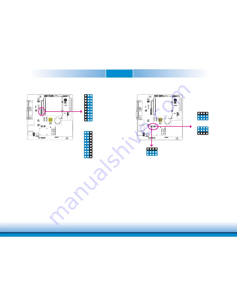
VGA/DVI Select

The system board allows connecting a device to either the DVI port or the VGA port at the 

rear panel. Use JP8 to select between using VGA or DVI.

JP8

A1-2, J1-2 On: 

VGA (default)

A2-3, J2-3 On: 

DVI

3

1

2

A

C

B

D

E

F

G

H

I

J

A

C

B

D

E

F

G

H

I

J

3

1

2

LAN2/PCIe x1 Slot Function Select

JP17 is used to select the function of PCIe x1 slot or LAN 2. JP18 is just used to select the 

LAN 2 function when pin 1 and 2 are set to On.

JP17

2-3 On: 

PCIe x1 slot (default)

3

1

2

1-2 On: LAN 2

3

1

2

JP18

1-2 On: 

LAN 2 (defaullt)

3

1

2

Содержание Q7-100

Страница 1: ...www dfi com Chapter 1 Introduction 1 Q7 100 Qseven Carrier Board User s Manual A19810337 ...

Страница 2: ... owners FCC and DOC Statement on Class B This equipment has been tested and found to comply with the limits for a Class B digital device pursuant to Part 15 of the FCC rules These limits are designed to provide reason able protection against harmful interference when the equipment is operated in a residential installation This equipment generates uses and can radiate radio frequency energy and if ...

Страница 3: ...t 12 VGA DVI Select 13 LAN 2 PCIe x1 Function Select 13 BIOS Select 14 Rear Panel I O Ports 15 Serial COM Ports 15 VGA Port 16 DVI I Port 16 RJ45 LAN Ports 17 Universal Serial Bus Connectors 17 Audio 18 Internal I O Connectors 18 S PDIF Connector 18 LVDS LCD Panel Connector and LCD Inverter Power Connector 19 Digital I O Connector and Digital I O Power Connector 20 Expansion Slots 20 SATA Serial A...

Страница 4: ...our system unit Static electrical discharge can damage computer components without causing any signs of physical damage You must take extra care in han dling them to ensure against electrostatic build up 1 To prevent electrostatic build up leave the system board in its anti static bag until you are ready to install it 2 Wear an antistatic wrist strap 3 Do all preparation work on a static free surf...

Страница 5: ...he information listed above This may differ in accordance with the sales region or models in which it was sold For more information about the standard package in your region please contact your dealer or sales representative Before Using the System Board Before using the system board prepare basic system components If you are installing the system board in a new system you will need at least the f...

Страница 6: ...Introduction Specifications Graphics Chrontel CH7317B SDVO to RGB DAC Audio Realtek ALC886 5 1 channel High Definition Audio Audio outputs Mic in Center Subwoofer line in surround and line out S PDIF audio interface Storage 2 SATA 3 0 ports with data transfer rate up to 6Gb s 1 SD MMC slot LAN 2 LAN ports LAN1 Gigabit Ethernet supported by the Qseven module LAN2 Realtek RTL8111DL PCIe Gigabit Ethe...

Страница 7: ...ect JP6 USB 4 5 power select JP5 LAN2 PCIe x1 Slot Function Select JP18 MXM 5V power select JP2 CAN bus Clear CMOS JP12 System fan USB 0 1 power select JP1 LCD Inverter power LVDS LCD panel CHRONTEL CH7317B Realtek ALC886 LVDS Power Select JP14 Battery Low COM0 2 Super IO Select JP16 USB 2 3 Power Select JP3 USB Host Client Select JP7 USB Client Backlight control level select JP15 BIOS Select J1 S...

Страница 8: ...nical Diagram 2 1 1 1 3 1 2 5 6 8 1 2 3 C A 1 17 0 00 10 16 46 94 154 94 160 02 0 00 17 75 36 91 59 43 89 62 125 71 151 78 157 48 163 83 6 35 1 57 0 00 6 35 157 48 163 83 160 02 154 94 22 86 10 16 54 80 148 65 68 30 122 30 149 90 134 90 100 90 85 90 149 90 85 90 ...

Страница 9: ...lecting 5V_standby will allow you to use a USB keyboard to wake up the system USB Power Select USB 0 1 JP1 1 3 2 1 3 2 2 3 On 5V_ standby 1 2 On 5V default USB 4 5 JP5 3 1 2 3 1 2 2 3 On 5V_standby 1 2 On 5V default 3 1 2 3 1 2 2 3 On 5V_standby 1 2 On 5V default USB 2 3 JP3 1 3 2 1 3 2 2 3 On 5V_ standby 1 2 On 5V default USB 6 7 JP6 Important If you are using the Wake On USB Keyboard Mouse funct...

Страница 10: ...fault values stored in the ROM BIOS please follow the steps below 1 Power off the system and unplug the power cord 2 Set JP12 pins 2 and 3 to On Wait for a few seconds and set JP12 back to its default set ting pins 1 and 2 On 3 Now plug the power cord and power on the system JP12 1 2 On Normal default 1 3 2 2 3 On Clear CMOS Data 1 3 2 Super IO Select JP6 1 3 2 2 3 On Disable default 1 3 2 1 2 On ...

Страница 11: ...trol Level Select 1 3 2 1 3 2 2 3 On 3 3V 1 2 On 5V default JP15 is used to select the backlight control level 5V or 3 3V JP15 MXM 5V Power Select 1 2 On 5VSB 6 4 2 5 3 1 6 4 2 5 3 1 6 4 2 5 3 1 3 4 On 5V 5 6 On NC JP2 is used to select the power of the MXM connector JP2 ...

Страница 12: ...ct 1 2 On 12V 6 4 2 5 3 1 6 4 2 5 3 1 6 4 2 5 3 1 3 4 On 5V 5 6 On 3 3V default JP14 is used to select the power of the LVDS connector JP14 USB Host Client Select JP7 is used to select between USB Host and USB client JP7 1 2 On USB Client 1 3 2 2 3 On USB Host default 1 3 2 ...

Страница 13: ...ct between using VGA or DVI JP8 A1 2 J1 2 On VGA default A2 3 J2 3 On DVI 3 1 2 A C B D E F G H I J A C B D E F G H I J 3 1 2 LAN2 PCIe x1 Slot Function Select JP17 is used to select the function of PCIe x1 slot or LAN 2 JP18 is just used to select the LAN 2 function when pin 1 and 2 are set to On JP17 2 3 On PCIe x1 slot default 3 1 2 1 2 On LAN 2 3 1 2 JP18 1 2 On LAN 2 defaullt 3 1 2 ...

Страница 14: ...www dfi com Chapter 2 Hardware Installation 14 Chapter 2 BIOS Select J1 is used to determine the BIOS boot device J1 1 2 On Boot from Carrier board SPI BIOS 1 1 1 2 Off Boot from Module SPI BIOS ...

Страница 15: ... 2 Line out VGA COM 1 DVI I DVI D signal LAN 1 LAN 2 USB 2 3 Mic in Center Subwoofer Line in Surround Serial COM Ports COM 1 COM 2 COM 1 and COM 2 RS232 The serial ports are RS232 asynchronous communication ports with 16C550A compatible UARTs that can be used with modems serial printers remote display terminals and other serial devices BIOS Setting Configure the serial ports in the Advanced menu o...

Страница 16: ...ws to hold the connector in place VGA Port VGA DVI I DVI D signal only The DVI I port is used to connect an LCD monitor This port supports DVI D signal only Connect the display device s cable connector to the DVI I port After you plug the cable con nector into the port gently tighten the cable screws to hold the connector in place BIOS Setting Configure the display device in the Chipset menu North...

Страница 17: ...dge bracket Install the card edge bracket to an available slot at the rear of the system chassis then insert the cable connector to a USB connector Wake On USB Keyboard The Wake On USB Keyboard function allows you to use a USB keyboard to wake up a system from the S3 STR Suspend To RAM state To use this function Jumper Setting JP4 must be set to 2 3 On 5V_standby Refer to USB Power Select in this ...

Страница 18: ...k is used to connect to the center and subwoofer speakers of the audio system Front audio Line out Mic in Center Subwoofer Line in Surround 10 AUD_HPRET_L AUD_HPRET_R AUD_GND AUD HPOUT L 5V Analog AUD_MIC_BIAS 9 1 AUD_HPOUT_R AUD_MIC 2 Key AUD_GND I O Connectors S PDIF Connector The S PDIF connector is used to connect external S PDIF ports Your S PDIF ports may be mounted on a card edge bracket In...

Страница 19: ...D panel LVDS LCD panel LCD Inverter power 1 8 2 1 40 39 LVDS LCD Panel Connector LCD Inverter Power Connector Pins Function Pins Function 1 GND 2 GND 3 LVDS_Out3 4 LVDS_Out7 5 LVDS_Out3 6 LVDS_Out7 7 GND 8 GND 9 LVDS_Out2 10 LVDS_Out6 11 LVDS_Out2 12 LVDS_Out6 13 GND 14 GND 15 LVDS_Out1 16 LVDS_Out5 17 LVDS_Out1 18 LVDS_Out5 19 GND 20 GND 21 LVDS_Out0 22 LVDS_Out4 23 LVDS_Out0 24 LVDS_Out4 25 GND ...

Страница 20: ...the PCI Express x1 slot Mini PCIe Slot Install mini PCI Express cards such as network cards or other cards that comply to the mini PCI Express specifications into the mini PCI Express x1 slot ExpressCard Slot The ExpressCard slot is an interface for high performance modular expansion It uses serial data interfaces PCIe x1 and USB that provide improve data transfer speed You can insert an ExpressCa...

Страница 21: ...and the other end to your Serial ATA device SATA Serial ATA Connectors SATA 0 SATA 1 7 1 TXN GND RXP RXN GND TXP GND Cooling Fan Connectors The fan connectors are used to connect cooling fans The cooling fans will provide adequate airflow throughout the chassis to prevent overheating the CPU and system board components System Fan 3 1 Sense Power Ground CPU Fan 1 3 Sense Power Ground ...

Страница 22: ...ion occurred an alarm will sound When the system s power is off and a chassis intrusion occurred the alarm will sound only when the system restarts 1 2 Ground Chassis signal Standby Power LED Standby Power LED This LED will lit red when the system is in the standby mode It indicates that there is power on the system board Power off the PC then unplug the power cord prior to installing any devices ...

Страница 23: ...12VDC Ground PS_ON NC 5VDC 5VDC ATX power Ground Ground Ground 5VDC Ground 3 3VDC 3 3VDC Ground 5VDC Ground 5VDC Ground 12VDC 3 3VDC Front Panel Connectors HDD LED HDD LED This LED will light when the hard drive is being accessed RESET SW Reset Switch This switch allows you to reboot without having to power off the system PWR BTN Power Switch This switch is used to power on or off the system PWR L...

Страница 24: ...ff Safety Measures Danger of explosion if battery incorrectly replaced Replace only with the same or equivalent type recommend by the manufacturer Dispose of used batteries according to local ordinance Battery Battery MXM Connector The MXM connector is used to interface the carrier board with a Qseven board Refer to the following page for the pin function of this connector MXM connector ...

Страница 25: ...1 1 3 A _B3 115 LVDS_ S D V L 6 1 1 3 A _B3 D N G 8 1 1 D N G 7 1 1 119 LVDS_A_ S D V L 0 2 1 K L C _B_CLK 121 LVDS_A_ S D V L 2 2 1 K L C _B_CLK 123 LVDS_BLT_CTRL GP_PWN_OUT0 124 RSVD 125 LVDS_DID_DAT GP_I2C_DAT 126 LVDS_BLC_DAT NC 127 LVDS_DID_CLK GP_I2C_CLK 128 LVDS_BLC_CLK NC 129 CAN0_ 0 N A C 0 3 1 X T _RX 131 SDVO_ O V D S 2 3 1 K L C B _INT NC 133 SDVO_ O V D S 4 3 1 K L C B _INT NC D N G 6...

Страница 26: ...and extended format The bit rate can be programmed to a maximum of 1Mbit s To connect the CAN controller module to the CAN bus it is necessary to add transceiver hardware When communicating in a CAN network individual message objects are configured The mes sage objects and the identifier masks for the receive filter for the received messages are stored in the message RAM Controller Area Network CA...

Страница 27: ...nd full speed 12Mbps operations It complies with USB 2 0 1 1 protocols 1 4 USB device detect USB data Ground 3 2 USB data SM Bus The SMBus System Management Bus connector is used to connect SMBus devices It is a multiple device bus that allows multiple chips to connect to the same bus and enable each one to act as a master by initiating data transfer 5 1 3VDU Data CLK ALERT GND ...

Страница 28: ...rmware hubs Trusted Platform Module TPM devices and embed ded controller solutions Data transfer on the LPC bus is implemented over a 4 bit serialized data interface which uses a 33MHz LPC bus clock For more information about LPC bus refer to the Intel Low Pin Count Interface Specification Revision 1 1 CLK 10 2 9 1 LAD1 RST LAD0 FRAME VCC3 LAD3 GND LAD2 SD MMC Slot This expansion port is used to i...

Страница 29: ... Pin Pin Assignment 1 3V_standby 2 Ground 3 CS 4 CK 5 SO 6 SI 7 HOLOD Battery Low This jumper is used to simulate the signal status that indicates the external battery is low By setting to pins 1 and 2 to On it sends a battery low signal to the module 1 2 Off Normal default 1 2 On Battery low 1 2 1 2 ...

Страница 30: ...he CD Autorun did not automatically start which is the Mainboard Utility CD screen did not appear please go directly to the root directory of the CD and double click Setup 1 Setup is now ready to install the audio driver Click Next 2 Follow the remainder of the steps on the screen clicking Next each time you finish a step 3 Click Yes I want to restart my computer now then click Finish Restarting t...

Страница 31: ... the installation 3 After completing installation click Finish 1 Setup is ready to install the driver Click Next Adobe Acrobat Reader 9 3 To install the reader click Adobe Acrobat Reader 9 3 on the main menu 1 Click Next to install or click Change Destination Folder to select another folder 2 Click Install to begin installation 3 Click Finish to exit installation ...

Отзывы: