


23
Chapter 5
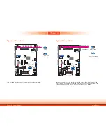
Chapter 5 Ports and Connectors
DC-in Power Connector
LAN 2
LAN 1
3
DDR3L
DDR3L
DDR3L
DDR3L
Mini PCIe with SIM
COM 4
RS232/RS422/RS485
12
10
3
1
JP22
1
1
1
(JP20)
(JP18)
(JP17)
(JP21)
1
3
12
10
COM 2
RS232/RS422/RS485
COM 1
RS232/RS422/RS485
USB 0
USB 3.0
HDMI
Reset
Power
39
40
2
1
LVDS LCD
Panel
USB 7
USB 6
Mic-in
1
Battery
Buzzer
1
Chassis
Intrusion
1
Clear CMOS
Data (JP24)
SPI
Flash
BIOS
eMMC
(optional)
iTE
IT8528E
Mini PCIe with LPC
mSATA
MicroSD
(optional)
1
System Fan
1
USB 0
Power
Select
(JP5)
1
2
5
6
(JP23)
1
1
1
(JP3)
(JP4)
1
2
10
9
COM 6
1
10
9
COM 5
1
1
USB 2 Power
Select (JP6)
USB 5-7 Power
Select (JP7)
1
2
10
9
USB 5
(JP25)
USB 2.0
USB 2.0
(JP17)
(JP20)
COM 4/DIO Select
(JP22, JP21)
Digital I/O 0-3 Output State
Digital I/O Power Select
Panel Power Select
(JP3)
(JP4)
(JP23)
Backlight Enable Power Select
Auto Power-on Select
(JP25)
Dimming Mode Select
(JP18)
Digital I/O 4-7 Output State
1
COM 3
RS232/RS422/RS485
4
1
(JP2)
(JP2)
LCD/Inverter Power Select
SATA 1
4
1 SATA
Power
1
SATA 2.0
I C
Line-out
DC-in
USB 2
USB 2
USB 2
USB 2
RJ45 LAN Ports
LAN 1
LAN 2
Features
• 2 Intel
®
I210AT PCI Express Gigabit Ethernet controllers
The LAN ports allow the system to connect to a local area network for Ethernet connectivity.
Driver Installation
Install the LAN drivers. Refer to Chapter 8 for more information.
LAN 2
LAN 1
3
DDR3L
DDR3L
DDR3L
DDR3L
Mini PCIe with SIM
COM 4
RS232/RS422/RS485
12
10
3
1
JP22
1
1
1
(JP20)
(JP18)
(JP17)
(JP21)
1
3
12
10
COM 2
RS232/RS422/RS485
COM 1
RS232/RS422/RS485
USB 0
USB 3.0
HDMI
Reset
Power
39
40
2
1
LVDS LCD
Panel
USB 7
USB 6
Mic-in
1
Battery
Buzzer
1
Chassis
Intrusion
1
Clear CMOS
Data (JP24)
SPI
Flash
BIOS
eMMC
(optional)
iTE
IT8528E
Mini PCIe with LPC
mSATA
MicroSD
(optional)
1
System Fan
1
USB 0
Power
Select
(JP5)
1
2
5
6
(JP23)
1
1
1
(JP3)
(JP4)
1
2
10
9
COM 6
1
10
9
COM 5
1
1
USB 2 Power
Select (JP6)
USB 5-7 Power
Select (JP7)
1
2
10
9
USB 5
(JP25)
USB 2.0
USB 2.0
(JP17)
(JP20)
COM 4/DIO Select
(JP22, JP21)
Digital I/O 0-3 Output State
Digital I/O Power Select
Panel Power Select
(JP3)
(JP4)
(JP23)
Backlight Enable Power Select
Auto Power-on Select
(JP25)
Dimming Mode Select
(JP18)
Digital I/O 4-7 Output State
1
COM 3
RS232/RS422/RS485
4
1
(JP2)
(JP2)
LCD/Inverter Power Select
SATA 1
4
1 SATA
Power
1
SATA 2.0
I C
Line-out
DC-in
USB 2
USB 2
USB 2
USB 2
Connect a DC power cord to this jack. Use a power adapter within 12~36V DC output voltage.
Using a power adapter that does not conform to the specified voltage may fail to boot the sys-
tem or cause damage to the system board.


