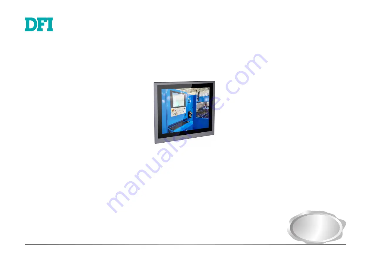
KS-KH Series
Modular-Designed Industrial Panel PC
User’s Manual
A-536-M-2002
Preliminary
Version
Страница 1: ...KS KH Series Modular Designed Industrial Panel PC User s Manual A 536 M 2002 Preliminary Version...
Страница 2: ...CC and DOC Statement on Class A This equipment has been tested and found to comply with the limits for a Class A digital device pursuant to Part 15 of the FCC rules These limits are designed to provid...
Страница 3: ...gs 17 Clear CMOS Data 17 PS 2 KB MS Power Select 17 COM1 COM2 RS232 Power Select 18 DIO Power Source Select Pins 0 7 18 COM1 COM2 RS232 422 485 Select 19 COM3 COM4 RS232 422 485 Select 20 Chapter 5 Po...
Страница 4: ...amage computer components without causing any signs of physical damage You must take extra care in han dling them to ensure against electrostatic build up 1 To prevent electrostatic build up leave the...
Страница 5: ...teries according to local ordinance Keep this system away from humidity Place the system on a stable surface Dropping it or letting it fall may cause damage The openings on the system are for air vent...
Страница 6: ...Features Model Name KS KH Processor 7th Generation Intel Core Processors BGA 1440 Chipset Intel CM238 QM175 Chipset LAN 2 LAN ports COM 4 COM ports Display VGA DVI D DVI I connector or HDMI HDMI or D...
Страница 7: ...to 70 C Relative Humidity 5 to 90 RH non condensing Shock Half sine wave 3G 11ms 3 shock per axis Construction Metal Aluminum Mounting Panel VESA Mount Mounting brackets and screws 2 optional Dimensio...
Страница 8: ...Connects the HDMI connector of an LCD monitor USB 3 0 Ports Connect all devices with USB Type A ports and support date rate according to USB 3 0 specification Gigabit LAN Ports Connect the system to a...
Страница 9: ...t Sensor On Off Press the Brightness up arrow for 3 seconds 3 OSD Lock Unlock Press the Brightness down arrow for 3 seconds 4 The Alarm LED will be red when the CPU temperature reaches 95 C 203 F Back...
Страница 10: ...e device in your operating environment 1 Power on the system 2 After the memory test the message Press DEL to run setup will appear on the screen Press the Delete key to enter the BIOS setup utility I...
Страница 11: ...s the case please turn the box module the other way around 3 Place the box module on top of the panel module with the alignment posts effortlessly slip ing into the designated holes on the box module...
Страница 12: ...r cords and cables 3 The 6 mounting screws on the left and right sides and bottom of the system are used to secure the cover to the chassis Remove these screws and put them in a safe place for later u...
Страница 13: ...n sert the memory into the socket at an angle and push it down until you feel a click Notes 1 The system supports dual channel configuration To enable dual channel popu late both SODIMM sockets 2 The...
Страница 14: ...ct the other end of the SATA data and power cable to the SATA data and power connectors on the system board respectively Mounting hole Mounting Screws The system can accommodate one SATA drive Please...
Страница 15: ...and use the provided mounting screw to secure the card on the system board If antenna cables are used route them to the antenna holes on the top panel of the system Installing a SIM Card Open the Min...
Страница 16: ...into the connector and then secure the card to the standoff with the provided mounting screw Mounting Screw The onboard M 2 Type 2280 connector M Key supports PCIe NVMe modules up to PCIe Gen 3 0 x4 b...
Страница 17: ...Power off the system and unplug the power cord 2 Set the jumper pins 2 and 3 to On Wait for a few seconds and set the jumper pins back to its default setting pins 1 and 2 On 3 Now plug the power cord...
Страница 18: ...in 1 and Pin 9 of COM1 and COM2 will vary accord ing to JP8 s and JP7 s setting respectively Refer to the next page for pin assignments of these COM ports 1 3 RI 2 4 DCD On RS232 default 3 5 5V 4 6 12...
Страница 19: ...On RS232 default 5 3 1 6 4 2 3 5 4 6 On RS422 Full Duplex RS485 6 4 2 5 3 1 3 5 2 4 On RS485 RS485 RS422 Full Duplex RS232 2 1 9 RXD DCD TXD DTR GND DSR RTS CTS RI 2 1 9 RXD RXD TXD TXD NC NC NC NC N...
Страница 20: ...C 1 23 4 5 1 3 4 6 On RS232 default 1 3 5 2 4 6 3 5 4 6 On RS422 Full Duplex 2 4 6 1 3 5 3 5 2 4 On RS485 1 3 5 2 4 6 Buzzer USB 3 4 USB 3 0 USB 1 2 USB 3 0 STB_LED PWR_BTN_1 HDMI default DP DVI 1 DC...
Страница 21: ...efer to Chapter 7 for more information USB 1 2 USB 3 4 USB 3 0 Buzzer USB 3 4 USB 3 0 USB 1 2 USB 3 0 STB_LED PWR_BTN_1 HDMI default DP DVI 1 DC in GLAN 2 GLAN 1 PCIe x16 PCIE1 SPI Flash BIOS 1 2 10 9...
Страница 22: ...JP10 1 2 10 COM 3 1 JP6 6 6 9 1 2 10 COM 2 9 1 2 JP7 JP14 6 6 1 2 1 2 10 COM 1 9 1 2 16 LPC 1 2 14 4 pin power 1 1 2 3 4 PCIe x4 PCIE2 Power Button Reset DDR4_2 SODIMM DDR4_1 SODIMM 1 JP5 6 6 1 1 1 6...
Страница 23: ...USB 1 2 USB 3 0 STB_LED PWR_BTN_1 HDMI default DP DVI 1 DC in GLAN 2 GLAN 1 PCIe x16 PCIE1 SPI Flash BIOS 1 2 10 9 9 USB 13 14 1 2 10 COM 4 VGA Clear CMOS Data JP1 PS 2 Power Select JP14 6 JP13 JP19...
Страница 24: ...anced menu Super IO Configuration submenu of the BIOS Refer to Chapter 7 for more information COM1 to COM4 RS232 RS422 RS485 USB Ports Buzzer USB 3 4 USB 3 0 USB 1 2 USB 3 0 STB_LED PWR_BTN_1 HDMI def...
Страница 25: ...JP7 COM 5 1 2 10 9 COM 6 1 2 10 9 21 JP4 PCIe x4 PCIE2 Reset DDR4_1 SODIMM DDR4_2 SODIMM 1 JP9 6 6 1 1 2 1 12 6 1 4 SATA Power 1 4 Power Button Power LED HDD LED M 2 Type 2280 PCIe LPC 1 2 14 1 1 DIO...
Страница 26: ...ctor and the other end to your storage device 12V 5V Ground 1 Ground 4 Buzzer USB 3 4 USB 3 0 USB 1 2 USB 3 0 STB_LED PWR_BTN_1 HDMI default DP DVI 1 DC in GLAN 2 GLAN 1 PCIe x16 PCIE1 SPI Flash BIOS...
Страница 27: ...COM 3 1 JP10 6 6 9 1 2 10 COM 2 9 1 2 JP11 JP17 6 6 1 2 1 2 10 COM 1 9 1 2 16 1 4 pin power 1 2 3 4 JP8 1 6 1 JP5 6 2 1 JP6 6 2 JP7 COM 5 1 2 10 9 COM 6 1 2 10 9 21 JP4 PCIe x4 PCIE2 Reset DDR4_1 SOD...
Страница 28: ...power is on this LED will light When the system is in the S1 POS Power On Suspend state it will blink every second When the system is in the S3 STR Suspend To RAM state it will blink every 4 seconds...
Страница 29: ...IM Mini PCIe 1 1 bettery 1 1 1 USB 2 0 SIM Mini PCIe 2 COM 2 COM 1 Front Audio 2 1 10 9 1 2 1 29 30 LVDS LCD Panel JP2 JP3 5 1 Front Panel 13 1 10 Mini PCI Express Slot with SIM card PCI Express x16 P...
Страница 30: ...2 3 4 JP8 1 6 1 JP5 6 2 1 JP6 6 2 JP7 COM 5 1 2 10 9 COM 6 1 2 10 9 21 JP4 PCIe x4 PCIE2 Reset DDR4_1 SODIMM DDR4_2 SODIMM 1 JP9 6 6 1 1 2 1 12 6 1 4 SATA Power 1 4 Power Button Power LED HDD LED M 2...
Страница 31: ...he Panel PC 2 Use the provided mounting screws to attach VESA mount bracket 1 to the wall VESA mount bracket 1 VESA mount bracket 2 VESA mount bracket 1 Mounting screw 3 Attach the other bracket VESA...
Страница 32: ...l it is properly fitted against the panel 4 Position the mounting clamps along the rear edges of the Panel PC and insert them into the slits around the Panel PC Note that the following diagram is for...
Страница 33: ...OS Setup Utility does not require an operating system to run After you power up the system the BIOS message appears on the screen and the memory count begins After the memory test the message Press DE...
Страница 34: ...from 00 to 59 System Date The date format is month date year Month displays the month from January to December Date displays the date from 1 to 31 Year displays the year from 1980 to 2099 Insyde BIOS...
Страница 35: ...en it s not 100 utilized Hyper Threading Enable Intel Hyper Threading Technology HT on the processor to improve per formance of operating systems and software that are optimized for hyper threading te...
Страница 36: ...devices PCI graphics devices PEG PEG PCIe Graphics devices connected to PEG lanes directly routed from the CPU PCIe graphics devices PCI graphics devices IGFX internal graphics PCI PCI graphics devic...
Страница 37: ...ll be unconditionally disabled Enabled High definition audio devices will be unconditionally enabled Auto High definition audio devices will be enabled if present and disabled otherwise SATA Configura...
Страница 38: ...es to use AHCI Advanced Host Controller Inter face Intel RST Premium This option allows you to create RAID using Intel Rapid Storage Technology It also al lows for the SATA controller to use the Intel...
Страница 39: ...I219 Mini PCIE1 M 2 For each PCIe root port above press Enter to configure its speed and hog plug function Enable Disable Enable or disable this PCI Express root port PCIe Speed Select the speed of t...
Страница 40: ...ology Support The section allows you to enable or disable the Intel Active Management Technology Intel AMT BIOS extension Refer to Chapter 10 Intel AMT Settings for more information Note that this fun...
Страница 41: ...setup utility Network Device List The Device Manager screen is displayed And if the Network Stack or the PXE Boot to LAN option is enabled from the Boot menu the Network Device List should be shown in...
Страница 42: ...0 and 255 Local Gateway Enter the gateway address in the IPv4 format Local DNS Domain Name System Servers Enter DNS Domain Name System server IP addresses in the IPv4 format IPv6 Network Configuration...
Страница 43: ...urned on and operate at the designated speed The range of the temperature is from 0 to 127o C Fan Speed Count 1 to Fan Speed Count 4 Set the fan speed The range is from 1 lowest speed 100 full speed C...
Страница 44: ...44 User s Manual KS KH Chapter 7 PC Health Status This section displays PC health information such as the voltages and CPU and system temperatures...
Страница 45: ...T_100 VT_UTF8 or PC_ANSI Baud rate 115200 57600 38400 19200 9600 4800 2400 or 1200 Data bits 8 bits or 7 bits Parity None Even or Odd Stop bits 1 bit or 2 bits Flow control None RTS CTS or XON XOFF Th...
Страница 46: ...Operation No changes to the current state Disable Disable and deactivate TPM Enable Enable and activate TPM Clear TPM Remove all TPM ownership contents Set Supervisor Password Set the administrative p...
Страница 47: ...function can only be enabled if the Network Stack support is enabled USB Boot Enable or disable booting to USB boot devices Quiet Boot Enable or disable the quiet boot function to configure the scree...
Страница 48: ...this field and press Enter to exit the BIOS setup without saving your changes Save Setting to file Select this option to save BIOS configuration settings to a USB drive The operation will fail if ther...
Страница 49: ...dated and will cease to be effective Updating the BIOS To update the BIOS you will need an updated BIOS file and a flash utility Please contact technical support or your sales representative for the f...
Страница 50: ...ry of the CD and double click Setup If your product package does not include a CD DVD you can download the latest drivers from the DFI Download Center http www dfi com DownloadCenter Once you are on t...
Страница 51: ...all the utility follow these steps 1 Setup is ready to install the utility Click Next to continue 2 Read the license agreement and then click Yes 5 Click Restart Now to allow the new software installa...
Страница 52: ...g before the Windows 7 Windows 8 1 Windows 10 desktop appears The blank screen period is the time Windows is testing the graphics performance We recommend that you skip this process by disabling this...
Страница 53: ...eparing to install the driver Click Next to continue 2 Click I accept the terms in the license agreement if you accept the agreement and then click Next 3 Select the program features you want to insta...
Страница 54: ...ese steps 1 You are about to install the driver Click Next to continue 2 Read the license agree ment and then click Next 4 Please wait while the prod uct is being installed 5 After the installation is...
Страница 55: ...then click Finish Restart the system allows the new software installation to take effect Audio Driver To install the audio driver follow these steps Intel Serial IO Driver To install Intel Serial IO...
Страница 56: ...ual KS KH Chapter 8 4 Setup is ready to install the driver Click Next to begin the installation 3 Read the file information and then click Next 5 Setup is now installing the driver 6 Click Finish to e...
Страница 57: ...power management for the storage subsystem You can also install and set up Intel Optane memory with the Intel Rapid Storage Technology application Audio Drivers To install the driver click Audio Drive...
Страница 58: ...all the driver Click Next to con tinue 2 Click I agree 3 Click Browse to install the driver in a different folder and select the folder Click Install to begin the installation 4 Setup is currently ins...