


www.dfi.com
23
Chapter 5 Ports and Connectors
Chapter 5
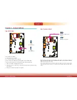
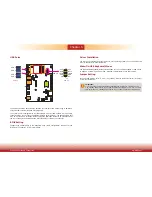
COM (Serial) Ports
COM 1 is fixed at RS485. COM 2 and COM 3 are fixed at RS232.
The serial ports are asynchronous communication ports with 16C550A-compatible UARTs that
can be used with modems, serial printers, remote display terminals, and other serial devices.
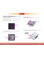
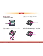
Connecting External Serial Ports
Your COM port may come mounted on a card-edge bracket. Install the card-edge bracket to
an available slot at the rear of the system chassis then insert the serial port cable to the COM
connector. Make sure the colored stripe on the ribbon cable is aligned with pin 1 of the COM
connector.
BIOS Setting
Configure the serial COM ports in the Advanced menu (“Super IO Configuration” submenu) of
the BIOS. Refer to the chapter 7 for more information.
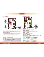
COM 3: RS232
2
1
9
RXD
DCD-
TXD
DTR-
GND
DSR-
RTS-
CTS-
RI-
COM 2: RS232
COM 1: RS485
2
1
9
DATA-
DATA+
GND
NC.
NC.
NC.
NC.
NC.
NC.
2
1
9
RXD
DCD-
TXD
D
TR-
GND
DSR
-
RT
S-
CT
S-
RI-
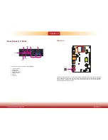
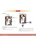
Front Panel Connector
HDD-LED - HDD LED
This LED will light when the hard drive is being accessed.
RESET-SW - Reset Switch
This switch allows you to reboot without having to power off the system.
PWR-BTN - Power Switch
This switch is used to power on or off the system.
PWR-LED - Power/Standby LED
When the system’s power is on, this LED will light. When the system is in the S1 (POS - Power
On Suspend) state, it will blink every second. When the system is in the S3 (STR - Suspend To
RAM) state, it will blink every 4 seconds.
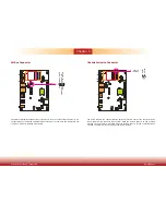
Pin Pin Assignment
Pin Pin Assignment
HDD-LED
3
HDD Power
PWR-LED
2
LED Power
5
Signal
4
LED Power
RESET-SW
7
Ground
6
Signal
9
RST Signal
PWR-BTN
8
Ground
11 N.C.
10
Signal
Front
Panel
HDD-LED
RESET-SW
PWR-LED
PWR-BTN
1
2
11
12
Note:
To make the RS485 auto flow control function work on COM 1, please set either 8
data bits + 1 stop bit or one of the following settings:
(1) 8 data bits + 1 parity bit + 1 stop bit
(2) 8 data bits + 1 parity bit + 2 stop bits
(3) 8 data bits + 2 stop bits
Содержание ES520-HU
Страница 1: ...www dfi com 1 Chapter 1 Introduction ES520 HU Desktop Box PC User s Manual A40200546...
Страница 29: ...www dfi com 29 Chapter 6 Mounting Options Chapter 6 5 00 8 50 16 00 80 00 182 60 5 00 8 50 16 00 80 00 182 60...
Страница 55: ...www dfi com 55 Chapter 8 Supported Software Chapter 8 HW Health Set DIO WatchDog...


