10
Chapter 2
HARDWARE INSTALLATION
User's Manual |
EB100-KU
X
Assembly
Overview
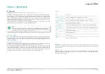
The system is assembled in the following procedure. To disassemble, please carry out the pro-
cedure in the reversed order.
1. Mount the board onto the top cover.
2. Attach the side cover.
3. Attach the front and rear panels.
4. Mount the SATA drive onto the SATA tray.
5. Mount the SATA drive tray and bottom cover.
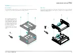
Bottom Cover and SATA Drive Tray
The internal I/O of the system is mainly ac-
cessed on the bottom side. The bottom metal
cover and the 2.5" SATA drive tray are secured
onto the chassis with 4 screws that go through
the front and rear panel metals. Use a Phillips
screwdriver to unscrew them.
The cable for SATA data and power shall be
connected first before assembly. Route the
cable in the manner that there is no contact
with heat generating chips and wafers.
Place the tray on a worksurface and place 2.5"
SATA drive onto the tray as illustrated. Align
the screw holes on the SATA drive to those on
the tray.
Fasten the screws and secure the drive onto
the tray as illustrated with four screws.
x4
x4
SATA Drive (optional)
The SATA Drive Tray can be mounted with a 2.5" SATA SSD and secured onto the system for
storage.


