


36
2
Hardware Installation
COM 1
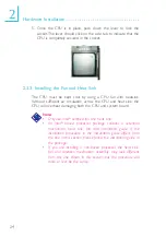
2.5.4 Serial Ports
W
W
1
9
2
CD
TD
RD
DTR
SG
RTS
DSR
CTS
RI
The system board is equipped with an onboard serial port (CN6
- Teal/Turquoise) for COM 1 and a 9-pin connector at location J7
for COM 2. These serial ports are RS-232C asynchronous com-
munication ports with 16C550A-compatible UARTs that can be
used with modems, serial printers, remote display terminals, and
other serial devices.
One card-edge bracket, mounted with a serial port cable, is pro-
vided with the system board. If you want to use the COM 2
serial port, connect the serial port cable to connector J7. Make
sure the colored stripe on the ribbon cable is aligned with pin 1
of connector J7. Mount the card-edge bracket to the system chas-
sis.
BIOS Setting
Select the serial ports’ I/O address in the Integrated Peripherals
submenu (“Super IO Device” field) of the BIOS. Refer to chapter
3 for more information.
COM 2


