Section 2 Direct Excitation (Brush Type)
Diagnostic Repair Manual
17
7.
While the unit is running and with jumper wires
connected to the brush assembly as described in
Steps 1, 2, and 3; connect one jumper wire to the
negative terminal of the battery and connect the
other jumper wire to the positive terminal.
8.
Record the voltage measured on the 240 VAC
receptacle panel. Approximately 130 VAC should
be measured. If no voltage is measured, connect
meter test leads across red and black wires at the
terminal block (TB).
9.
Set RUN-STOP switch to STOP.
10.
Disconnect meter leads from 240 VAC receptacle.
11.
. Connect one meter test lead to the
blue excitation winding wires.
12.
Set RUN-STOP switch to RUN and start unit.
13.
While the unit is running and with jumper wires
connected to the brush assembly as described in
Steps 1, 2, and 3; connect one jumper wire to the
negative terminal of the battery and connect the
other jumper wire to the positive terminal.
14.
Record voltage measured on blue excitation
winding wires. Approximately 60 VAC should be
measured.
15.
Set RUN-STOP switch to STOP.
16.
Set DMM to measure resistance.
17.
Connect the meter test lead to one jumper wire and
connect the other meter test lead to the other
jumper wire to measure resistance of the brushes
and the rotor. Refer to chart for resistance. If the
correct resistance was not measured, remove
brushes and measure resistance across the slip
rings. If resistance is measured, inspect or replace
brushes. If resistance was NOT measured across
the slip rings, replace rotor.
18.
Set DMM to measure DC amperage. Refer to
Section 1.2 “Measuring Current.”
NOTE:
Inspect the fuses in the meter to ensure test
results will be correct.
19.
Connect one meter test lead to the positive jumper
wire.
20.
Set RUN-STOP switch to RUN and start unit.
21.
Connect the negative jumper wire to the negative
terminal on the battery and connect the meter test
lead not connected to anything to the positive
terminal.
NOTE:
The meter should now be connected in series
with the positive jumper wire.
22.
Record DC amperage measured. Approximately
0.22 DC amps should be measured.
NOTE:
The DC voltage of the battery divided by the
resistance measured in Step 17 will give a calculated
amp draw.
23.
Set RUN-STOP switch to STOP.
24.
Repeat Step 21 while the unit is OFF. The DC
amperage measured should be the same as step
22 ± 0.10 DC amps.
25.
Set DMM to measure resistance.
26.
Connect the meter test leads to the green and
white sensing wires. The resistance reading should
be as referenced in the specifications.
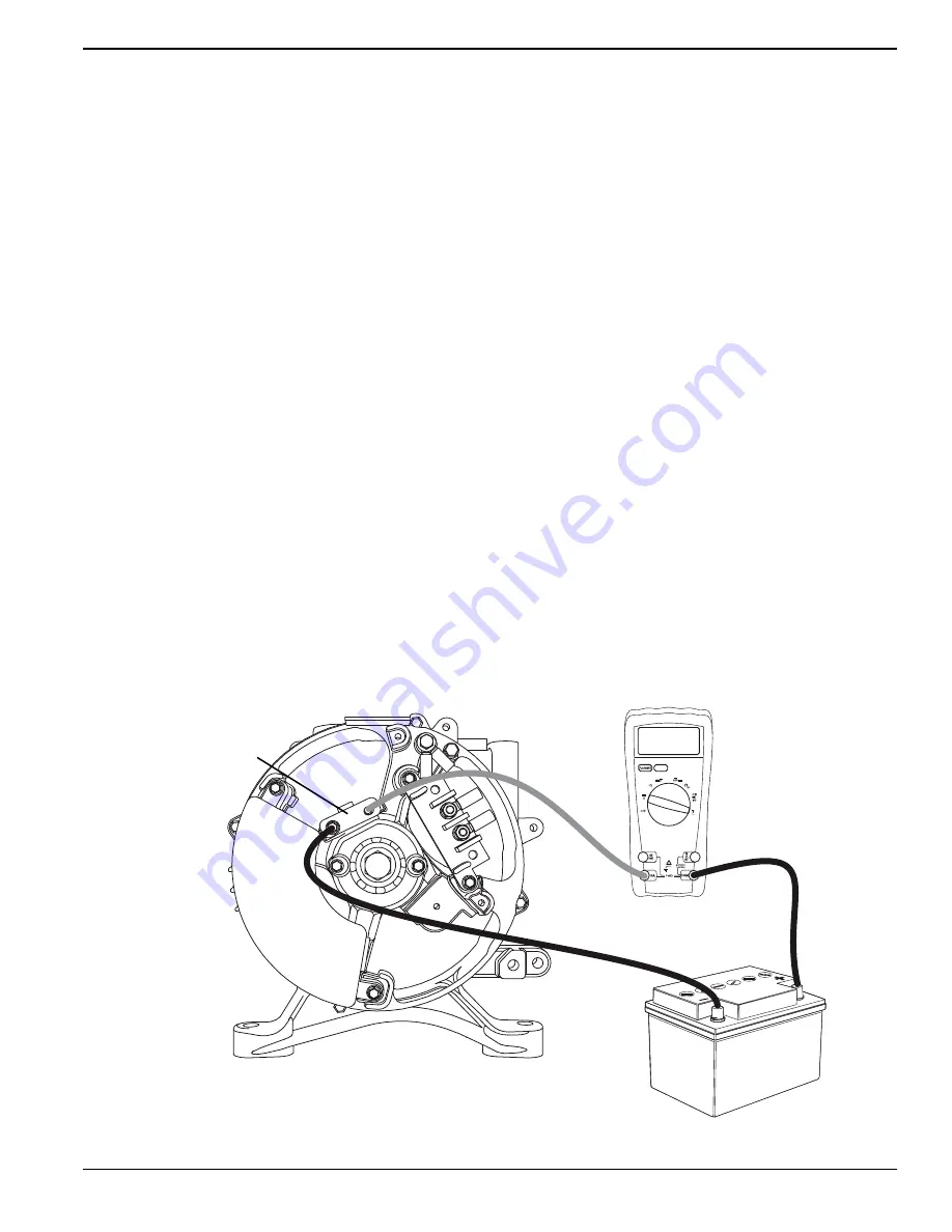
Figure 2-9. Jumper Wire and DMM Between Battery and Brush Assembly
!MPS
!62
"253(!33%-",9
6/,4
"!44%29
003972
Содержание DXGN14000
Страница 44: ...Section 4 Major Disassembly 40 Diagnostic Repair Manual Exploded View DXGNR7000 ...
Страница 48: ...Section 5 Electrical Data 44 Diagnostic Repair Manual Wiring Diagram and Electrical Schematic DXGN4500 004157 ...
Страница 49: ...Section 5 Electrical Data Diagnostic Repair Manual 45 Wiring Diagram and Electrical Schematic DXGN6000 004163 ...
Страница 50: ...Section 5 Electrical Data 46 Diagnostic Repair Manual Wiring Diagram and Electrical Schematic DXGN7200 004179 ...
Страница 51: ...Section 5 Electrical Data Diagnostic Repair Manual 47 Wiring Diagram and Electrical Schematic DXGN14000 004431 ...
Страница 53: ...Section 5 Electrical Data Diagnostic Repair Manual 49 Wiring Diagram and Electrical Schematic DXGNR7000 ...
Страница 54: ...Section 5 Electrical Data 50 Diagnostic Repair Manual ...
Страница 55: ......


