background image

5

English

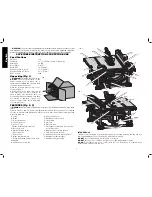
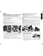
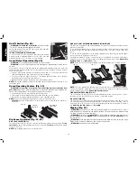
POSITIONING THE BLADE GUARD ASSEMBLY/RIVING KNIFE (FIG. 5, 6)
To position the blade guard assembly:

WARNING: 

Use the blade guard assembly for all thru-sawing.

  1. Raise the saw blade arbor to its maximum height.
  2. Install blade guard assembly by pulling the riving knife/guard release lever (L) and inserting 

splitter (M) until it bottoms out.

 3.  

Release lever, make sure clamp plates are fully closed and the splitter is clamped securely.

NOTE:

 Pull on the blade guard assembly/riving knife to ensure it has locked into place.

WARNING: 

Use the riving knife for non thru-sawing when blade guard assembly cannot 

be used.

NOTE:

 Follow steps 1–3 to install the riving knife (W) in the same manner as the blade guard 

assembly, Refer to figure 24.

WARNING: 

Before connecting the table saw to the power source or operating the saw, 

always inspect the blade guard assembly and riving knife for proper alignment and clearance 
with saw blade. Check alignment after each change of bevel angle.

 WARNING:

  To reduce the risk of serious personal injury, DO NOT operate saw if riving knife 

or blade guard assembly is not securely clamped in place.

When properly aligned, the blade guard assembly/riving knife will be in line with the blade at 
both table top level, and at the top of the blade. Using a straight edge, ensure that the blade 
(B) is aligned with the riving knife (W) or the splitter (M). With power disconnected, operate the 
blade tilt and height adjustments through the extremes of travel and ensure the blade guard 
assembly clears the blade in all operations and that the anti-kickback assembly is functioning.

FIG. 6

M

B

FIG. 7

K

FIG. 5

L

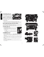
To remove the blade guard assembly/riving knife (FIG. 5, 7)

  1. Pull the riving knife/guard release lever (L).
  2. Lift up on blade guard assembly(K)/riving knife (W).

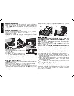
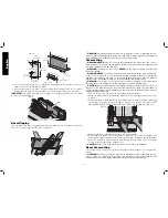
TO ASSEMBLE THE THROAT PLATE (FIG. 8)

  1. Align the throat plate (Q) as shown in Figure 8,

FIG. 8

CC

DD

Q


and insert the tabs on the back of the throat 
plate into the holes on the back of the table 
opening.

  2. Rotate cam counterclockwise until the front 

of throat plate drops into place. Secure 
by rotating cam lock knob (CC) clockwise 
1/4 turn (when cam lock is under the table 
holding the throat plate in place).

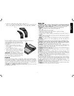
  3. The throat plate includes four adjustment screws which raise or lower the throat plate. 

When properly adjusted, the front of the throat plate should be flush or slightly below the 
surface of the table top and secured in place. The rear of the throat plate should be flush 
or slightly above the table top.

ASSEMBLY

WARNING: Shock Hazard. To reduce the risk of serious personal injury, turn unit 

off and disconnect machine from power source

 before

 attempting to move it, change 

accessories or make any adjustments. 

An accidental start-up can cause injury.

THIS SAW SHOULD BE ASSEMBLED IN THE FOLLOWING ORDER: (FIG, 2, 4)

  1. Make sure blade is installed correctly and arbor nut is tight. Use wrenches (U) stored on 

the tool. Refer to Figure 3.

  2. Install and lock throat plate (Q). (

NOTE:

 Adjust leveling screws before proceeding. Refer 

to 

To Assemble the Throat Plate

.)

  3. Attach the rip fence (R). (

NOTE: 

Adjust rip scale before proceeding. Refer to


Adjusting 

Rip Scale

.

)

  4. Position the blade guard assembly.
  5. Attach anti-kickback assembly to the guard assembly.

NOTE:

 To attach this table saw to a stand, please follow the instructions included with the 

stand assembly.
Tools needed for assembly include the wrenches included with this saw.

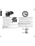
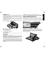
ATTACHING/REPLACING THE BLADE (FIG. 2, 4)

  1. Raise the saw blade arbor to its maximum height by turning the blade height adjustment 

wheel (F) clockwise.

  2. Remove the arbor nut (Z) and flange (BB) from the saw arbor by turning counterclockwise.

BB

Z

FIG. 4

AA

U

B

  3. Place the saw blade on to the spindle (AA) making sure the teeth of the blade (B) point down 

at the front of the table. Assemble the flange and arbor nut to the spindle and tighten arbor 
nut (Z) as far as possible by hand, making sure that the saw blade is against the inner washer 
and the flange (BB) is against the blade. Ensure the largest diameter of the flange is against 
the blade. Ensure the spindle and flange are free from dust and debris.

  4. To keep the spindle from rotating when tightening the arbor nut, use the open end of the 

wrench (U) to secure the spindle.

  5. Using the arbor wrench, tighten the arbor nut (Z) by turning it clockwise.
 6. 

NOTE: 

Different types of blades make different kerfs (width of cuts). Therefore, it is 

necessary to check adjustment of rip scale when changing blades. Replacement blade 
MUST not exceed the thickness stated on the riving knife. The riving knife provided with 
the saw is 2.2 mm thick.

Содержание dwe7491rs

Страница 1: ... PÓLIZA DE GARANTÍA ADVERTENCIA LÉASE ESTE INSTRUCTIVO ANTES DE USAR EL PRODUCTO Before returning this product call 1 800 4 DEWALT IF YOU SHOULD EXPERIENCE A PROBLEM WITH YOUR DEWALT PURCHASE CALL 1 800 4 DEWALT IN MOST CASES A DEWALT REPRESENTATIVE CAN RESOLVE YOUR PROBLEM OVER THE PHONE IF YOU HAVE A SUGGESTION OR COMMENT GIVE US A CALL YOUR FEEDBACK IS VITAL TO THE SUCCESS OF DEWALT S QUALITY I...

Страница 2: ......

Страница 3: ... and adjusting wrenches are removed from spindle before turning tool on Tools scrap pieces and other debris can be thrown at high speed causing injury KEEP WORK AREA CLEAN Cluttered areas and benches invite accidents DO NOT USE THE MACHINE IN A DANGEROUS ENVIRONMENT The use of power tools in damp or wet locations or in rain can cause shock or electrocution Keep your work area well lit to avoid tri...

Страница 4: ...rmation is also available from the National Safety Council 1121 Spring Lake Drive Itasca IL 60143 3201 Please refer to the U S Department of Labor OSHA 1910 213 Regulations metal prongs when unplugging or plugging in the cord An accidental start up can cause injury REDUCE THE RISK OF UNINTENTIONAL STARTING Make sure that the switch is in the OFF position before plugging in the power cord In the ev...

Страница 5: ...MANUAL AND YOU SHOULD BECOME FAMILIAR WITH THEM Thru sawing refers to any cut that completely cuts through the workpiece Non thru sawing refers to any cut that does not completely cut through the workpiece Push Stick refers to a wooden or plastic stick usually homemade that is used to push small workpiece through the saw and keeps the operator s hands clear of the blade Kickback occurs when the sa...

Страница 6: ...able saw is completely assembled and you have read the entire instruction manual Open the box and slide the saw out as shown in Figure 1 Carefully unpack the table saw and all loose items from the carton Examine all parts to make sure that parts have not been damaged during shipping If any parts are missing or damaged contact your dealer to replace them before attempting to assemble the tool FEATU...

Страница 7: ...The throat plate includes four adjustment screws which raise or lower the throat plate When properly adjusted the front of the throat plate should be flush or slightly below the surface of the table top and secured in place The rear of the throat plate should be flush or slightly above the table top ASSEMBLY WARNING Shock Hazard To reduce the risk of serious personal injury turn unit off and disco...

Страница 8: ...10 percent or more will cause a loss of power and overheating All DEWALT tools are factory tested If this tool does not operate check the power supply TO REMOVE THE THROAT PLATE 1 Remove the throat plate Q by turning the cam lock knob CC 1 4 turn counterclockwise 2 Using finger hole DD on the plate pull throat plate up and forward to expose the inside of the saw DO NOT operate the saw without the ...

Страница 9: ...osition 2 locator pins then using the blade wrench holes as a guide for positioning align the pins Fig 23 3 Tighten the locator pins front and rear FIG 19 G OO F NN MM FIG 20 FIG 21 POSITION 1 POSITION 2 FIG 22 DD ADJUSTMENTS WARNING To reduce the risk of injury turn unit off and disconnect machine from power source before installing and removing accessories before adjusting or changing set ups or...

Страница 10: ...width marked on the blade or on the blade packaging The splitter and riving knife thickness must be greater than the body thickness and less than the kerf width as shown in Figure 26 RIVING KNIFE THICKNESS KERF WIDTH WIDTH OF CUT MADE BY THE BLADE BODY OR PLATE THICKNESS OF THE BLADE FIG 26 FIG 23 DD U ALIGNING RIVING KNIFE TO BLADE FIG 24 1 Remove the throat plate Refer to Remove Throat Plate und...

Страница 11: ...ll times to reduce the risk of a thrown workpiece and possible injury There are two basic types of cutting with table saws ripping and crosscutting Regardless of material man made or natural wood the distinction between ripping and crosscutting is as follows Ripping is cutting to a different width usually with the grain and crosscutting describes cutting material across the shorter dimension usual...

Страница 12: ...is tilted away from the fence and hands WARNING Keep hands clear of the blade On Off Switch Fig 29 WARNING To reduce the risk of injury be sure the switch is in the OFF position before plugging machine in Pull the red paddle H to turn this saw on and push down the red paddle to turn the saw off LOCK OFF FEATURE INSTRUCTIONS To lock the saw off insert a padlock underneath the paddle A padlock with ...

Страница 13: ... or slightly lower than the saw table CAUTION Never push or hold onto the free or cut off side of the workpiece if it is between the blade and the fence Ripping Small Pieces Fig 34 It is unsafe to rip small pieces It is not safe to put your hands close to the blade Instead rip a larger piece to obtain the desired piece When a small width is to be ripped and the hand cannot be safely put between th...

Страница 14: ...mly against the miter gauge with the path of the blade in line with the desired cut location Keep the workpiece an inch or so in front of the blade KEEP BOTH HANDS AWAY FROM THE BLADE AND THE PATH OF THE BLADE Fig 39 FIG 39 4 Start the saw motor and allow the blade to come up to speed 5 While using both hands to keep the workpiece against the face of the miter gauge and holding the workpiece flat ...

Страница 15: ...lade guard assembly not touching the blade before starting the motor CAUTION Certain workpiece shapes such as molding may not lift the blade guard assembly properly Feed the workpiece slowly to start the cut If the blade guard assembly contacts the blade place the workpiece under the blade guard assembly not touching the blade before starting the motor This operation is the same as crosscutting ex...

Страница 16: ...ication Fig 44 1 All motor bearings are permanently lubricated at the factory and no additional lubrication is needed 2 The height adjustment screw may require periodic cleaning and lubrication If you have difficulty raising or lowering the blade a Unplug the saw b Turn the saw on its side so the bottom open part of the unit is accessible c Clean and lubricate the height adjustment screw threads Z...

Страница 17: ... and replacement should be performed by a DEWALT factory service center a DEWALT authorized service center or other qualified service personnel Always use identical replacement parts Register Online Thank you for your purchase Register your product now for WARRANTY SERVICE Registering your product will help you obtain more efficient warranty service in case there is a problem with your product CON...

Страница 18: ... lame couteau diviseur et dispositif anti rebonds au cours des opérations pour lesquelles ils ont été conçus et ce pendant toute la durée de coupe FONCTIONNALITÉ DE DÉTECTION DE CARTER cette scie est équipée d un système de détection indiquant à l utilisateur si le carter est installé correctement RETIRER TOUTE CLÉ ET TOUT OUTIL DE RÉGLAGE Vérifier systématiquement que toute clé ou outil de réglag...

Страница 19: ... autres bijoux qui pourraient se prendre dans les pièces mobiles Il est recommandé de porter des chaussures antidérapantes Couvrir ou attacher les cheveux longs PORTER SYSTÉMATIQUEMENT DES LUNETTES DE PROTECTION Utiliser aussi un masque antipoussières si la découpe doit en produire beaucoup Les lunettes ordinaires ne peuvent que protéger contre les impacts et ne sont pas des lunettes de protection...

Страница 20: ...avec des tailles d encoches différentes pour les ajuster à l épaisseur de la pièce Se reporter à la photo d un poussoir de fin de passe en troisième de couverture La forme peut varier selon vos besoins tant que celui ci remplira sa fonction de protéger vos mains de la lame NE JAMAIS REMETTRE LA MACHINE EN MARCHE quand la pièce à machiner se trouve contre la lame et ce pour réduire tout risque d ex...

Страница 21: ...s que possible b S assurer que le guide longitudinal est bien parallèle à la lame c Ne pas découper longitudinalement en appliquant la force d avance à la section de la pièce à travailler qui est destinée à devenir la chute Pour une coupe longitudinale la force d avance doit systématiquement être appliquée entre la lame et le guide Utiliser un bâtonnet pour pousser les pièces étroites de 152 mm 6 ...

Страница 22: ...u maçonnerie NE PAS l utiliser en milieu ambiant humide ou en présence de liquides ou de gaz inflammables NE PAS la laisser à la portée des enfants Une supervision est nécessaire auprès de tout utilisateur non expérimenté MONTAGE AVERTISSEMENT risques de chocs électriques Pour réduire tout risque de dommages corporels graves arrêter et débrancher la machine du secteur avant de la déplacer de chang...

Страница 23: ...la broche Y en vous assurant que les dents de lame B sont orientées vers le bas et l avant de la table Insérez la bride et l écrou d arbre sur la broche et resserrez manuellement l écrou d arbre X autant que possible en vérifiant bien que la lame se trouve contre la rondelle interne et la rondelle AA de large diamètre contre la lame Assurez vous bien que le diamètre le plus large de la bride se tr...

Страница 24: ...eplaqué avec des serre joints à votre établi chaque fois que vous voudrez vous servir de la scie INSTALLATION DU GUIDE LONGITUDINAL FIG 11 13 Le guide longitudinal peut être installé sur deux positions à droite Position 1 pour coupes longitudinales de 0 à 24 5 po et Position 2 pour coupes longitudinales de 8 à 32 5 po et une position à gauche de la scie de table 1 Déverrouillez les verrous du guid...

Страница 25: ...if Une baisse de tension de 10 pour cent ou plus causera perte de puissance et surchauffe Tous les outils DEWALT sont testés en usine Si l outil ne fonctionne pas correctement vérifiez la source d alimentation Réglages AVERTISSEMENT pour réduire tout risque de dommages corporels arrêter et débrancher la machine du secteur avant d installer ou retirer tout accessoire avant tout réglage ou changemen...

Страница 26: ...compris diamant ne doivent pas être utilisées avec cette scie Sélection du couteau séparateur et couteau diviseur Fig 26 à 28 AVERTISSEMENT pour minimiser tout risque de rebonds et assurer une coupe adéquate le couteau séparateur et le couteau diviseur doivent avoir l épaisseur adaptée à la lame utilisée Le couteau séparateur et le couteau diviseur fournis avec cette scie de table sont adaptés à l...

Страница 27: ...oute réparation Tout démarrage accidentel comporte des risques de dommages corporels AVERTISSEMENT avant d utiliser la scie vérifier systématiquement les éléments suivants Porter SYSTÉMATIQUEMENT un équipement de protection oculaire auditif et respiratoire adéquats La lame est fermement serrée Les boutons de verrouillage d angle de biseau et de hauteur de coupe sont verrouillés En cas de coupes lo...

Страница 28: ...nstaller ou retirer tout accessoire avant tout réglage ou changement de configuration ou pour faire toute réparation Tout démarrage accidentel comporte des risques de dommages corporels AVERTISSEMENT avant de brancher le banc de scie circulaire sur le secteur ou d utiliser la scie inspecter systématiquement l alignement le fonctionnement et l espace entre la lame et le dispositif de carter de lame...

Страница 29: ...s de fin de passe Un poussoir de fin de passe V est inclus avec cette scie et rattaché au guide longitudinal Utilisez le les poussoir s de fin de passe pour maintenir la pièce contre la table et le guide et pousser complètement la pièce au delà de la lame FIG 31 FIG 32 D E A4 A3 REMARQUE ce guide permet au dispositif de protection de rester sur la scie pour effectuer des coupes longitudinales étro...

Страница 30: ...tes Cela laissera un espace suffisant pour utiliser un bloc poussoir TT reportez vous à la section Bloc poussoir 1 Suivez le schéma en Figure 35 pour fabriquer un guide longitudinal auxiliaire étroit SS REMARQUE sa longueur devrait être similaire à celle du dessus de la table de scie et ses côtés TT devraient être parallèles 9 5 mm 3 8 25 mm 1 1 2 12 7 mm FIG 35 TT SS 121 mm 4 3 4 9 5 mm 3 8 2 Une...

Страница 31: ... le dispositif de carter de lame et le couteau diviseur Vérifier l alignement après chaque changement d angle de biseau Coupes transversales AVERTISSEMENT NE JAMAIS toucher le bout libre de la pièce à machiner ou la chute qui est coupée alors que le moteur est en MARCHE et ou que la lame est toujours en rotation Le morceau pourrait entrer en contact avec la lame être violemment rejeté et poser des...

Страница 32: ...u couteau diviseur carter de lame et tirez le carter ou le couteau diviseur vers le haut pour le retirer Lors de l utilisation d une scie à rainure le tampon spécial de lame dado vendu aussi comme accessoire doit être utilisé Chaque fois qu une coupe requise est considérablement plus large que le trait de scie la scie à rainure est utilisée L engravure est utilisée couramment pour soutenir et soul...

Страница 33: ...e carter de lame Reportez vous à la section Retrait du dispositif de carter de lame Insérez le dispositif de carter de lame dans son logement comme illustré puis tournez le levier vers la gauche pour le verrouiller 3 Appuyez sur la goupille du dispositif anti rebonds N pour permettre à l ensemble de sortir de la fente du couteau diviseur 4 Installez le dispositif anti rebonds dans son logement com...

Страница 34: ...plus ne pas utiliser d essence de térébenthine ou de diluant de produits de nettoyage à sec ou tout autre produit similaire qui pourrait sérieusement endommager les pièces en plastique S assurer qu aucun liquide ne pénètre dans l outil ne jamais immerger aucune partie de l outil dans un liquide Accessoires AVERTISSEMENT puisque les accessoires autres que ceux offerts par DEWALT n ont pas été testé...

Страница 35: ...operaciones para las cuales puedan utilizarse incluyendo el corte tangencial completo CARACTERÍSTICA DE DETECCIÓN DEL PROTECTOR Esta sierra está equipada con un sistema de detección que indica al usuario cuando el protector está instalado correctamente QUITE LAS LLAVES DE AJUSTE Hágase el hábito de comprobar que la herramienta no tenga ninguna llave de ajuste puesta antes de encenderla Herramienta...

Страница 36: ...n las piezas móviles Se recomienda el uso de calzado antideslizante Cúbrase y recójase el pelo si lo tiene largo USE SIEMPRE LENTES DE SEGURIDAD Utilice también careta o mascarilla si en la operación se produce polvo Los anteojos de uso diario solo tienen lentes resistentes a golpes NO son anteojos de seguridad TRABAJE CON SEGURIDAD Utilice abrazaderas o tornillos para sujetar la pieza de trabajo ...

Страница 37: ...e la sierra y la guía utilice un empujador para piezas de trabajo estrechas de 152 mm 6 pulg de anchura o menos d Mantenga la unidad del protector de la hoja de la sierra el cuchillo divisor y la unidad anti rebote en su sitio y asegúrese de que funcionen bien Si la unidad anti rebote no JAMÁS REALICE LA DIAGRAMACIÓN ENSAMBLADO O AJUSTE DEL TRABAJO SOBRE la banco área de trabajo cuando la máquina ...

Страница 38: ...riales son usualmente bastante duros y resbalosos puede que los seguros anti rebote no detengan un rebote Por lo tanto usted debe ser especialmente cuidadoso en seguir los procedimientos de ajuste y corte adecuados para el ranurado f Utilice el ensamble protector de la hoja de sierra el ensamble anti rebote y la cuchilla en toda operación para la cual puedan ser usados incluyendo corte tangencial ...

Страница 39: ... la guía para cortes longitudinales R NOTA Ajuste la escala para cortes longitudinales antes de continuar Consulte Ajuste de la escala para cortes longitudinales 4 Posicione la unidad del protector de la hoja 5 Instale la unidad anti rebote en la unidad del protector NOTA Para instalar esta sierra de banco a un soporte siga las instrucciones incluidas con la unidad del soporte Entre las herramient...

Страница 40: ...je apriete la tuerca de eje X girándola en sentido horario 6 NOTA Distintos tipos de hoja hacen distintos cortes anchura de cortes Por lo tanto es necesario comprobar el ajuste de la escala de cortes longitudinales al cambiar las hojas La hoja de repuesto no DEBE exceder el grosor indicado en el cuchillo divisor El cuchillo divisor suministrado con la sierra tiene 2 2 mm de grosor POSICIONAMIENTO ...

Страница 41: ...nuación para ajustar la sierra Una vez realizados estos ajustes deberá mantenerse su precisión Tómese un poco de tiempo ahora para seguir estas instrucciones con cuidado para mantener la exactitud de lo que es capaz esta sierra AJUSTE DEL BLOQUEO DE RIEL FIG 2 17 Ajuste del sistema de sujeción de la guía 1 Trabe la palanca de bloqueo de riel E 2 Afloje la tuerca en la parte inferior de la sierra J...

Страница 42: ... Ensamblaje AJUSTE DE LA ALINEACIÓN DE LA HOJA FIG 18 Hoja Paralela a Ranura DE Inglete ADVERTENCIA Peligro de Corte Revise la hoja a 0 y 45 para asegurarse que no pega contra la placa de garganta provocando lesiones personales Si la hoja esta desalineada con la ranura de inglete en la parte superior de la banco se requerirá de una calibración para su alineación Para realinear la hoja y la ranura ...

Страница 43: ...ulg MIN ancho DE línea de corte y 1 75 mm 0 067 pulg MAX espesor DE cuerpo ALINEACIÓN DE LA CUCHILLA CON LA HOJA FIG 24 1 Cambie la placa de garganta Ver Remoción de la Placa de Garganta en Ensamblaje 2 Lleva la hoja hasta su profundidad máxima de corte y a 0 de ángulo de bisel 3 Localice el juego de cuatro tornillos pequeños PP adyacente a la perilla de bloqueo de la cuchilla QQ Estos tornillos s...

Страница 44: ...aterial la madera natural o artificial la distinción entre el corte longitudinal y el tronzado es la siguiente El corte longitudinal es un corte de una anchura diferente normalmente al hilo y el tronzado describe cortar material a través de una dimensión más corta normalmente contra el hilo ADVERTENCIA Al cortar longitudinalmente utilice siempre la guía para proporcionar una orientación para el ma...

Страница 45: ...cortes longitudinales agregue 50 mm 2 pulg Consulte Ajuste de la escala para cortes longitudinales bajo Montaje Interruptor de encendido y apagado Fig 29 ADVERTENCIA Para reducir el riesgo de lesión asegúrese de que el interruptor esté en posición de apagado antes de enchufar la máquina Tire de la palanca roja H para encender la sierra y empuje hacia abajo la palanca roja para apagar la sierra INS...

Страница 46: ...NCIA Debe usarse SIEMPRE una guía para cortes longitudinales para operaciones de cortes longitudinales a fin de evitar la pérdida de control y las lesiones corporales No realice NUNCA una operación de corte longitudinal a mano alzada Bloquee SIEMPRE la guía en el riel ADVERTENCIA Cuando se hagan cortes longitudinales biselados y siempre que sea posible coloque la guía a un lado de la hoja para que...

Страница 47: ...uía y coloque la escuadra de inglete en la ranura deseada 2 Ajuste la altura de la hoja de tal forma que la hoja quede a 3 2 mm 1 8 pulg por encima de la parte superior de la pieza de trabajo 3 Sujete firmemente la pieza de trabajo contra la escuadra de inglete con el paso de la hoja en línea con el lugar de corte deseado Mantenga la pieza de trabajo a una pulgada o un poco más del frente de la ho...

Страница 48: ...mble anti rebote y la cuchilla FIG 39 4 Encienda la sierra y permita que la hoja adquiera velocidad 5 Mientras utilice ambas manos para mantener la pieza de trabajo contra la cara de la escuadra de inglete y sujete la pieza de trabajo en posición plana contra la banco empuje lentamente la pieza de trabajo a través de la hoja 6 Jamás intente traer de vuelta la pieza de trabajo con la hoja girando A...

Страница 49: ...Y está disponible como accesorio por un costo adicional Consulte la sección Accesorios AVISO Debe tenerse cuidado al colocar las mangueras de manera que no obstaculicen la operación de corte Después de un uso prolongado el sistema de recolección de polvo de la sierra puede estar bloqueado Para limpiar el sistema de recogida de polvo 1 Desenchufe la sierra 2 Ponga la sierra de costado de forma que ...

Страница 50: ...es apague la máquina y desconéctala del suministro eléctrico antes de instalar y quitar accesorios y antes de hacer ajustes cambios de configuración o reparaciones La puesta en marcha accidental puede causar lesiones Limpieza ADVERTENCIA El soplar polvo y virutas fuera de la caja externa del motor usando aire comprimido limpio y seco es un procedimiento de mantenimiento regular necesario El polvo ...

Страница 51: ...w dewalt com o dirígase al centro de servicio más cercano Esta garantía no aplica a accesorios o a daños causados por reparaciones realizadas o intentadas por terceros Esta garantía le otorga derechos legales específicos además de los cuales puede tener otros dependiendo del estado o la provincia en que se encuentre Además de la garantía las herramientas DEWALT están cubiertas por 1 AÑO DE SERVICI...

Страница 52: ...se venden en América Latina Para los productos que se venden en América Latina debe consultar la información de la garantía específica del país que viene en el empaque llamar a la compañía local o visitar el sitio Web a fin de obtener esa información REEMPLAZO GRATUITO DE LAS ETIQUETAS DE ADVERTENCIAS Si sus etiquetas de advertencia se vuelven ilegibles o faltan llame al 1 800 4 DEWALT 1 800 433 9...

Страница 53: ......

Страница 54: ......

Страница 55: ......

Страница 56: ...ouper ATENCIÓN fabrique varas de empuje de madera contrachapada o madera blanda cuyo ancho sea igual o menor que el ancho del material que desea cortar Push Stick Pattern Modèle de poussoir Patrón de la vara de empuje Adjust length of push stick so hand will clear blade guard and rip fence Régler la longueur du poussoir de sorte que la main sera dégagée du protège lame et du guide longitudinal Aju...

Отзывы: