12
GB
5.
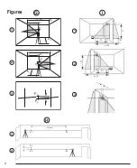
Place the laser 2”–3” (5–8 cm) from the second wall. To test
the front laser dot, make sure the front of the laser is facing
the wall (Figure
K
#2), and adjust the height of the laser
until the laser dot hits point P2.
6.
Turn the laser 180˚ and aim the laser dot near point P1 on
the first wall, and mark point P3
(Figure
K
#2).
7.
Measure the vertical distance between points P1 and P3 on
the first wall.
8.
If your measurement is greater than the
Allowable
Distance Between P1 & P3
for the corresponding
Distance Between Walls
in the following table, the laser
must be serviced at an authorized service center.
Distance Between
Walls
Allowable Distance
Between P1 & P3
20′ (6.0m)
9/64” (3.6mm)
30′ (9.0m)
7/32” (5.4mm)
50′ (15.0m)
11/32” (9mm)
75′ (23.0m)
9/16” (13.8mm)
9.
Repeat steps 2 through 8 to check the accuracy of the right
dot and then the left dot, making sure that the laser dot you
are testing is the laser dot facing each wall.
Level Dot Accuracy - Square
Checking the level calibration of the laser unit requires
a room
at least 35’ (10m) long
. A
ll marks can be made on the floor
by placing a target in front of the level or square beam and
transferring the location to the floor.
NOTE
:
To ensure accuracy, the distance (D1) from P1 to P2, P2
to P3, P2 to P4, and P2 to P5 should be equal.
1.
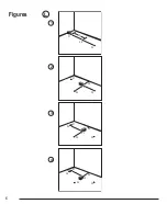
Mark point P1 on the floor at one end of the room, as
shown in Figure
L
#1.
2.
Turn the laser ON and press
once to display dots above,
ahead, and below the laser
.
3.
Place the laser so that the down dot is centered over point
P1 and make sure the front dot points toward the far end of
the room (Figure
L
#1).
4.
Using a target to transfer the front level dot location on the
wall to the floor, mark point P2 on the floor and then point P3
on the floor (Figure
L
#1).
5.
Move the laser
to point P2 and align the front level dot to
point P3 again (Figure
L
#2).
6.
Using a target to transfer the front level dot location on the
wall to the floor, mark the location of two square beams as
points P4 and P5 on the floor
(Figure
L
#2).
7.
Turn the laser
90° so the front level dot aligns to point P4
(Figure
L
#3).
8.
Mark the location of the first square beam as point P6 on
the floor as close as possible to point P1 (Figure
L
#3).
9.
Measure the
distance between points P1 and P6 (Figure
L
#3).
10.
If your
measurement is greater than the
Allowable
Distance Between P1 & P6
for the corresponding
Distance (D1)
in the following table, the laser must be
serviced at an authorized service center.
Distance (D1)
Allowable Distance Between
P1 & P6
25’ (7.5m)
3/32” (2.2mm)
30’ (9m)
7/64” (2.7mm)
50’ (15m)
3/16”(4.5mm)
11.
Turn the laser
180° so the front level dot aligns to point P5
(Figure
L
#4).
12.
Mark the location of the second square beam as point P7
on the floor as close as possible to point P1 (Figure
L
#4).
13.
Measure the
distance between points P1 and P7 (Figure
L
#4).
14.
If your
measurement is greater than the
Allowable
Distance Between P1 & P7
for the corresponding
Distance (D1)
in the following table, the laser must be
serviced at an authorized service center.
Distance (D1)
Allowable Distance Between
P1 & P7
25’ (7.5m)
3/32” (2.2mm)
30’ (9m)
7/64” (2.7mm)
50’ (15m)
3/16”(4.5mm)
Содержание DCE0825G
Страница 1: ...DEWALT5DotCrossLineLaser DCE0825R DCE0825G GB NL GR I FIN D DK ES NO F SE PT TR www DEWALT eu ...
Страница 2: ...1b 1a 3a 3b 3c 3d 3e 3f x3 x2 x1 x2 x3 x1 x2 Figures 2 1 2 A B C 1 2 1 4 20 5 8 11 3 3 ...
Страница 3: ...3 D E F DCB121 DCB123 DCB127 ...
Страница 5: ...5 J K P2 P2 P3 P1 P1 x x x x x 1 2 P1 P2 P3 P1 P2 x x x x x 20 6m 1 2 ...
Страница 6: ...Figures 6 4 L P1 P2 P3 D1 P1 P2 P5 P4 P3 P1 P6 P2 P5 P4 P3 P7 P1 P6 P2 P5 P4 P3 1 2 3 ...
Страница 128: ...DEWALT Industrial Tool Co DCE0825R DCE0825G N498957 Jan 2017 Copyright 2017 DeWALT http www DeWALT eu ...


