Devon & Devon Claridge, Руководство по сборке
Скачайте Бесплатно сборочную инструкцию для продукта Devon & Devon Claridge на нашем веб-сайте. Получите подробное руководство по сборке изделия, чтобы легко и быстро собрать его. Посетите наш manualshive.com и загрузите необходимый руководство сейчас.
Поделиться
Скачать


Отзывы:
Нет отзывов
Похожие инструкции для Claridge
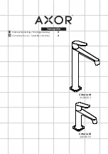
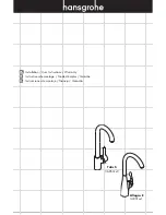
Metris S 31100000
Бренд: Hans Grohe Страницы: 290
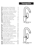
Logis M31 260 1jet 71835000
Бренд: Hans Grohe Страницы: 44
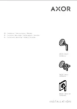
Axor Citterio M 34120003
Бренд: Hans Grohe Страницы: 12
Axor Citterio
Бренд: Hans Grohe Страницы: 20
Talis S
Бренд: Hans Grohe Страницы: 16
PuraVida 15070 1 Series
Бренд: Hans Grohe Страницы: 20

Ondus 31 047
Бренд: Grohe Страницы: 20

SD35B
Бренд: Nemaxx Страницы: 20

Support Washbasin
Бренд: Ropox Страницы: 16

Croma 220 Air 1jet 26465 Series
Бренд: Hans Grohe Страницы: 3

Wynd 816/348 Series
Бренд: JADO Страницы: 2

Vernis Blend 230 V 71504007
Бренд: Hans Grohe Страницы: 16

Raindance Select E 120 Eco
Бренд: Hans Grohe Страницы: 40

ShowerSelect 15760003
Бренд: Hans Grohe Страницы: 16

OCEAN W6
Бренд: WimTec Страницы: 40

NINA
Бренд: BOX DOCCIA Страницы: 2

Pure Stone Wood 98M1 61
Бренд: Villeroy & Boch Страницы: 2

K-8359
Бренд: Kohler Страницы: 28


