background image

Appendix  

|

|

 devolo MicroLink ISDN i 

|

64

EN

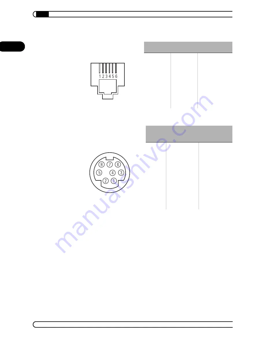
RJ11 socket contact assignments

Mini-DIN 8 socket pin assignments

S

0

 socket

 Line

IAE

1
2
3
4
5
6

-
T+
R+
R-
T-
-

-
2a
1a
1b
2b
-

DIN

 Mini DIN 8

Explanation
(USA)

Mini DIN 8

E1
E2
D1
D2
M1
M2
M3
M5
S1.1
S1.2
S2


U
5
3
6
1
4
7

8
2

GND
GND
TxD
RxD
DSR
CTS
RI
DCD

DTR
RTS

Содержание MicroLlink

Страница 1: ...MicroLink ISDN i...

Страница 2: ...written authorization from devolo We reserve the right to make any alterations that arise as the result of technical development Trademarks Windows Windows NT and Microsoft are registered trademarks o...

Страница 3: ...vided This documentation was compiled by several members of our staff from a variety of departments in order to ensure you the best possible support when using your devolo product Additional informati...

Страница 4: ...irective R TTE and is designed for connection to public telecommunications networks in the EU and Switzerland Connect the device to the public telecommunications network with the sup plied cable The d...

Страница 5: ...trolling 11 2 3 2 Additional controlling 11 2 4 Overview of the AT command set 12 3 AT commands Detailed description 15 3 1 Description of registers 35 3 2 Description of messages 52 3 2 1 Commands wi...

Страница 6: ...ructions of the hardware wiz ard The MicroLink ISDN i driver contains information e g device name connect ing messages initialization commands for your Windows operating system It could also be found...

Страница 7: ...to one ISDN S0 interface Status displays LED displays at the front of the ISDN modem permit the monitoring of the ISDN connection and the line to facilitate trouble shooting of possible system faults...

Страница 8: ...to enter these commands consecu tively in a single command line after an introductory AT and to conclude the line with an M The individual commands may be separated by spaces to improve the over view...

Страница 9: ...mand line in an escape sequence is restricted to a maximum of 40 characters The command AT F loads the firmware default parameter settings The ISDN modem is thus reset to its factory defaults This co...

Страница 10: ...you with frequently used AT commands and registers to change the configuration of your modem The column Commands and registers lists AT commands and registers to change the basic settings of the mode...

Страница 11: ...tween command and transmission phase ATO S2 Control of call signaling ATL ATM Selection of modem information ATI ATS AT V AT R AT S AT V S86 Control of error correction AT ES Control of dial lock or d...

Страница 12: ...CTS always active DSR always active and CTS tracks DCD DSR tracks transmission channel and CTS tracks DCD E0 E1 Commands not echoed Commands echoed F Load default configuration F Dialing of stored te...

Страница 13: ...s m 0 to 9 Q0 Q1 Q2 Return of messages from ISDN terminal adapter on Return of messages from ISDN terminal adapter off Messages off in answer mode Q0 Q1 CONNECT message after invalid escape sequence N...

Страница 14: ...plete configuration profile X0 X1 X2 X3 X4 Busy signal returns NO CARRIER Busy signal returns NO CARRIER Busy signal returns NO CARRIER Busy signal returns BUSY Busy signal returns BUSY X0 X1 XON XOFF...

Страница 15: ...d manually if automatic call answering has been set as the call establishment will be aborted by the entry of any character other than a line feed see register S0 Call establishment is not aborted how...

Страница 16: ...sables DTR dialing AT D1 Enables DTR dialing When DTR dialing is enabled and the condition of the control line switches from OFF to ON the MicroLink ISDN i establishes a connection to the number Speci...

Страница 17: ...ion the ON to OFF DTR transition aborts the connection If the MicroLink ISDN i is in the trans mission phase i e with an existing connection it will switch to the com mand phase With AT D2 the transit...

Страница 18: ...hardware flow control is used the AT D command setting has no effect on the CTS signal line in the transmission phase E Command Echo to Host ATE0 Commands not echoed ATE1 Commands echoed This command...

Страница 19: ...icroLink ISDN i is in the command mode after an escape command or a DTR transition from ON to OFF with a preceding AT D1 H2 Call rejected ATH2 If ATH2 is input in response to an incoming RING the call...

Страница 20: ...o select the operating mode of the MicroLink ISDN i The ISDN modem attempts to establish an error corrected X 75 connection by default If the remote station does not support X 75 the adapter automati...

Страница 21: ...ault ICI Charge information AT ICI Display charge information AT ICI p 0 Delete charge information for port This command is used to display the total connect charges as well as the connect charges for...

Страница 22: ...is entered on the MicroLink ISDN i IDBS Setting the data block length AT IDBS Value1 Value2 Value3 This command is used to set the data block length It can be used to ensure compatibility to other B c...

Страница 23: ...using an ISDN point to point connection IEAZ Setting the terminal selection digit EAZ AT IEAZ p EAZ This command is only relevant for the German national protocol 1TR6 If the command is entered in the...

Страница 24: ...ill be answered regardless of the target dial number specified for the incoming call A maximum of three caller IDs can be stored The caller ID may consist of a maximum of 20 digits 0 to 9 No further c...

Страница 25: ...used to reset all ISDN settings to factory default The current ISDN configuration of the terminal adapter may be displayed using the AT I command ISCI Service characteristics for incoming analog calls...

Страница 26: ...ed using the AT W or AT W commands The fol lowing settings are valid Example To set the MicroLink ISDN i for Group 3 fax operation enter the following command AT ISCO 0 3 The MicroLink ISDN i is set t...

Страница 27: ...mmand AT M has no effect O Transition to online status ATO The command ATO can be used to switch back into the transfer mode to resume online data transmission if the MicroLink ISDN i is in the comman...

Страница 28: ...in answer mode With this command messages to the attached computer by the ISDN modem can be completely suppressed ATQ1 or suppressed in the answer mode only ATQ2 Q Message after return to transfer ph...

Страница 29: ...he MicroLink ISDN i continues to receive from the telephone line the data is temporarily stored in the receive buffer If the send buffer of the MicroLink ISDN i is full it switches the CTS Clear To Se...

Страница 30: ...to control the period of time after which the MicroLink ISDN i automatically breaks the connection if no data has been sent in the mean time The default value 0 switches the inactivity timer off UPX F...

Страница 31: ...messages AT V1 Identification of connections with error correction AT V2 Additional distinction of correction processes AT V8 Detailed CONNECT messages With the setting AT V0 call establishment messag...

Страница 32: ...s switched off Registers for which the current value cannot be saved using the command AT W are saved with their default values W Save complete configuration profile AT Wn Save complete configuration...

Страница 33: ...selected see also AT Q When AT X0 is set the XON XOFF characters are used solely to control the data flow between the local MicroLink ISDN i and the computer and are not sent to the remote system Whe...

Страница 34: ...number stored at location m The command AT Z corresponds to the command AT P The numbers stored with the command AT Z can thus be overwritten with the command AT P see also the command AT P The comma...

Страница 35: ...Please refer to the following description for the significance of the registers S0 Automatic call answering The automatic answering of calls can be set in the register S0 If S0 0 every incoming call...

Страница 36: ...mmand which is used to switch from the transfer phase to the command phase can be changed in register S2 The transition to the command phase is blocked by values 127 S3 Carriage return characters The...

Страница 37: ...option The contents of register S14 is stored in the nonvolatile memory with the commands AT W or AT W The individual bits have the following signifi cance Valid values 0 to 127 decimal Default value...

Страница 38: ...in text ATV1 4 5 0 0 Reserved 6 0 0 Polling not possible during call establish ment the call establishment is aborted by any characters other than LF XON and XOFF 64 1 Polling possible during call est...

Страница 39: ...i cance The values in bit 4 and 5 are overwritten with each AT command issued unless the automatic bit rate identification is switched off in register S51 Bit Dec Description Command 0 3 0 Reserved 4...

Страница 40: ...he following signifi cance S51 Bit oriented option The contents of register S51 is stored in the nonvolatile memory with the commands AT W or AT W The individual bits have the following signifi cance...

Страница 41: ...ers are sent AT X1 5 6 0 0 Reserved 7 0 0 Automatic bit rate identification on 128 1 Automatic bit rate identification off Bit Dec Description Command Bit Dec Description Comman d 0 1 0 0 DSR always a...

Страница 42: ...ion ATZ 32 1 Serial speed is not modified during reinitiali zation ATZ 6 7 0 0 Reserved Bit Dec Description 0 7 3 3 Computer side bit rate 300 bps 4 4 Computer side bit rate 600 bps 5 5 Computer side...

Страница 43: ...ce Bit Dec Description Command 0 3 0 0 CONNECT messages not modified AT V0 1 1 Identification of error free connections AT V1 2 2 Differentiation of MNP V 42 AT V2 8 8 Detailed acknowledgment AT V8 4...

Страница 44: ...ith the S151 reg ister 3 0 0 Display of messages in plain text German 8 1 Display of messages in plain text English 4 7 0 0 Reserved Bit Dec Description Bit Dec Description 0 4 0 No ISDN connection 8...

Страница 45: ...ority No signaling delay takes place with the default value 0 S153 CONNECT NO CARRIER message The contents of register S153 can be stored with the commands AT W or AT W The individual bits have the fo...

Страница 46: ...n the signaling channel D channel for every 250 data packets This register can be read only The contents of this register can only be reset by switching the adapter off and back on 2 0 0 No display of...

Страница 47: ...S158 describes which B channel is currently in use or which one was used last This register can be read on S159 Status of the S0 interface Register S159 contains the current status of the ISDN S0 int...

Страница 48: ...000 00h No call was pending 016 10h Call currently being signaled 017 11h Call answered 018 12h Call attempt ended or answered by another device on the S0 bus 032 20h Call had incorrect Service Indic...

Страница 49: ...ervice Indicator and the Additional Service Indicator of the last connection or the last incoming call if the con nection attempt failed These registers can be read only The coding is effected as 1TR6...

Страница 50: ...s used to select the operating mode of the MicroLink ISDN i The individual bits in register S180 have the following significance Bit Dec Description 0 1 0 0 Answer digital calls 1 1 Answer analog call...

Страница 51: ...el protocol The agreed B channel protocol can be displayed in register S194 after the establishment of a connection This register can be read only 14 14 X 75 V 120 18 18 V 120 HDLCP 5 7 0 0 Reserved B...

Страница 52: ...of the incoming call if this has not been sup pressed by the remote station Register S153 can be used to set whether this number should be displayed together with the RING and or CONNECT mes sage Exam...

Страница 53: ...re influenced by the AT M AT V and ATX commands NO CARRIER The cause of the failed connection may also be displayed together with the NO CARRIER message see also register S153 Example NO CARRIER 053 0...

Страница 54: ...ter terminal operational DTR Data Terminal Ready The effect of this control line on the MicroLink ISDN i is determined by the command AT D Switch on transmission RTS Request To Send Operational DSR Da...

Страница 55: ...of connection aborted by character input dur ing establishment Input of characters during establishment of connection not permitted If the input of characters is to be permitted during call establishm...

Страница 56: ...vel 2 possible sources of errors If applicable test the modem directly at the NT net work terminator 051 007 Abort of D channel level 3 Verify the selected D channel protocol AT IDP 051 008 Connection...

Страница 57: ...ween these subscribers SPC must be requested from network operator 052 181 Target number service or serv ice characteristic incorrect Check the dial number and the enabling of the desired services als...

Страница 58: ...not accepted 053 016 Normal call trigger 053 017 Remote station busy 053 018 No response from remote station 053 019 Remote station does not answer 053 021 Call rejected 053 022 Dial number has chang...

Страница 59: ...53 066 Channel type not implemented 053 069 Requested characteristic does not exist 053 070 Data transfer service available only 053 079 Service or option does not exist 053 088 Remote station does no...

Страница 60: ...tatus display Green and yellow LEDs on the front panel of the ISDN terminal adapter serve as the status display of the ISDN connection S0 status S0 line Power TxD D1 Data or command from local PC to I...

Страница 61: ...ted TEI assigned State of LED Description Off Blinking slowly once per sec total 2 to 3x Blinking quickly 3x per sec Constantly lit No call no connection Incoming call terminal device is not responsib...

Страница 62: ...ween X 75 V 120 and PPP synchronous Command set Advanced AT command set Operating surveillance 9 LEDs S0 status S0 line Power TxD transmit data RxD receive data DTR data terminal ready RTS request to...

Страница 63: ...the electric current flows back via the interface ground following the lowest resistance Normally this does not cause problems Security Integrated watchdog Environment Temperature 0 55 C humidity 0 80...

Страница 64: ...cket contact assignments Mini DIN 8 socket pin assignments S0 socket Line IAE 1 2 3 4 5 6 T R R T 2a 1a 1b 2b DIN Mini DIN 8 Explanation USA Mini DIN 8 E1 E2 D1 D2 M1 M2 M3 M5 S1 1 S1 2 S2 U 5 3 6 1 4...

Страница 65: ...tspricht complies with the appropriate essential requirements of the FTEG Article 3 of R TTE and the other relevant provisions Harmonisierte Normen Gesundheit und Sicherheit gem 3 1 1 Artikel 3 1 a Ha...

Страница 66: ...rranty services carried out by devolo do not result in an extension of the warranty period nor do they initiate a new warranty period The warranty period for in stalled replacement parts ends with the...

Страница 67: ...intentional act or culpable negligence c Claims for compensation of lost profits indirect or consequential detriments are excluded d devolo is not liable for lost data or retrieval of lost data in cas...

Отзывы: