Page 8 SB-6-159-H
MINIMUM PIPE SIZE RECOMMENDATIONS ChART
Compressor
Compressor
Main
Min. Pipe
Size
Capacity
Air Line
Diameter
1-1/2 and 2 HP 6 to 9 CFM
Over 50 ft.
3/4"
3 and 5 HP
12 to 20 CFM
Up to 200 ft.
3/4"
Over 200 ft.
1"
5 to 10 HP
20 to 40 CFM
Up to 100 ft.
3/4"
100 to 200 ft.
1"
Over 200 ft.
1-1/4"
10 to 15 HP
40 to 60 CFM
Up to 100 ft.
1"
100 to 200 ft.
1-1/4"
Over 200 ft.
1-1/2"
CLEANAIR™ AIR PIPINg RECOMMENDATIONS
The plumbing of your shop air lines is very important. Correct
installation is necessary for the proper performance of your
equipment - for an uncontaminated air supply and for sufficient
pressure to your breathing apparatus and spray gun.
Correct air line piping is so important that this one factor alone
can reduce contaminates in your air supply up to 75%. Reduc-
ing contaminates to the filter also reduces the frequency of filter
replacement, maintenance, and of course reduces the risk of
contaminates to the painter and paint supply.
Even the size of the pipe is critical. Using pipe that is too small
in diameter can cause a pressure drop.
Example: If an air compressor delivers 100 psi through a 100'
pipe 1/2" in diameter, there's greater pressure drop than if a 3/4"
diameter pipe were used. The chart on the back page provides
recommended piping sizes..
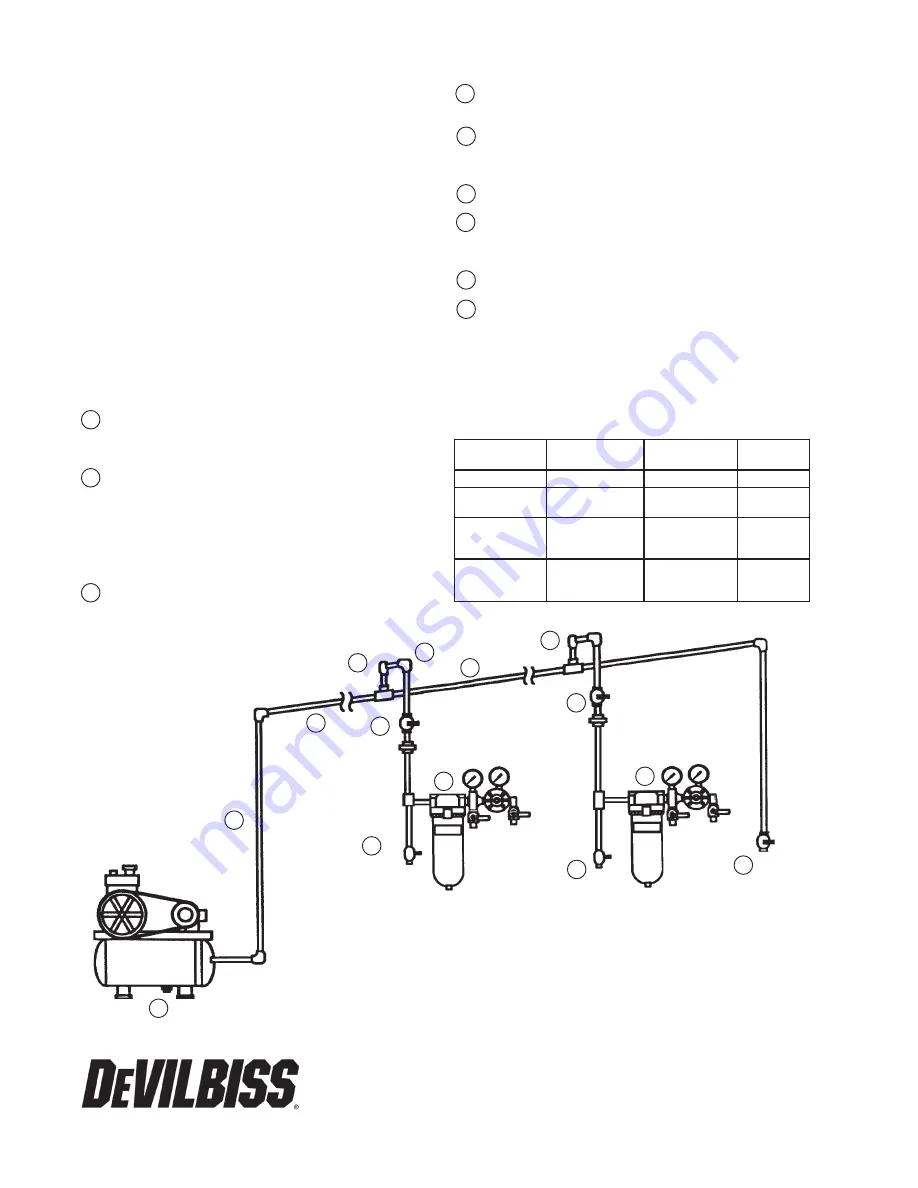
AIR LINE PIPINg gUIDE
1 After leaving the air compressor, the air line should go
straight up as high as possible. This helps prevent any water
from leaving the compressor and travelling through the
pipe.
2 Horizontal pipes should slope back towards the compressor
at least 4" per 50'. As warm air leaves the compressor, it
cools and thereby water vapor condenses as it travels
through the pipe. This water, a problem in itself, also can
cause scaling and rust inside the piping. The backward
sloping of the pipe helps drain these contaminates back
toward the compressor drain which should be drained
daily.
3 A take off should come from the top of the main air supply
line at each air drop. This reduces the risk of water and other
contaminates from traveling down the drop into the water
separator.
4 Pipe diameter must be of sufficient size for the volume of
air being passed as well as the length of pipe used. This
will minimize pressure drop. See chart.
5 First air drop should be at least 25' from the compressor,
although 50' is optimum. This allows the compressed air
to cool so any condensation can occur before it gets to the
air filter.
6 Shut-off valves are installed before the point of use filter.
This allows air to be shut off for filter maintenance.
7 Point-of-use filter - Strongly recommended for eliminating
any remaining contaminates. The DeVilbiss CleanAir type
air control units are most effective in providing a truly
contaminant-free air supply.
8 Drain valve - The daily draining of the system at each outlet
disposes of the contaminants that build up in the air supply.
9 Drain the compressor trap daily if equipped with a manual
drain.
Proper maintenance of the air compressor can reduce airborne
contaminants such as particles and oils, and reduce heat and
operating cost. Check air filters, oil level and perform regular
maintenance per operators manuals.
1
6
5
8
3
2
6
9
8
For normal
compressed
air systems
having average
amounts of
airborne con-
taminants.
Add final
drain leg for
extremely
wet/dirty air.
Add drain leg with
blow down valve at
each station when
compressed air is
extremely wet/dirty.
Figure 13 - CleanAir™ Piping
4
8
7
7
3
5/12 ©2012 DeVilbiss All rights reserved. Printed in U.S.A.


