


11
3 OPERATION
3.1 START-UP
Before starting up the unit, be sure to check that the following
items are in compliance:
1.
The electrical installation, the oil supply system, the
venting system, combustion air supply and ventilation;
2.
The blower access door is in place and the blower rail
locking screws are well tightened;
3.
The Blocked Vent Shut-Off (BVSO) is installed according
to instructions (for chimney venting);
4.
The oil supply valve is open;
5.
The burner ‘’Reset’’ button is well pushed in or re-armed;
6.
The preliminary air adjustments on the burner
comply
with the technical specifications in this manual;
7.
The blower speed adjustments for heating and air
conditioning are appropriate and according to the
specifications in this manual;
8.
The blower start/stop delays are satisfactory;
9.
The thermostat of the room is in the heating mode and is
set higher than the ambient temperature.
To start the unit, turn the main electrical switch on.
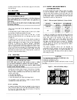
3.2 OPERATING
SEQUENCE
OIL
HEATING
MODE
1.
The W-R contact closes;
2.
The burner motor starts up to pre-purge the combustion
chamber for a period of 10 to 15 seconds. During that time
a spark is established on the electrodes;
3.
The solenoid valve opens and a flame is established.
Shortly after, the electrodes cease to spark;
4.
Then the blower runs up to full speed. The delay depends
on the adjustments that were made on the electronic
board, which controls the blower motor. Refer to Sections
2.11 and 2.12 above as well as the airflow tables for more
details.
5.
When the call for heat is satisfied, the solenoid valve
closes, the flame goes out and the burner motor stops
(after post purge delay, if applicable).
6.
The blower stops shortly after the burner. The delay
depends on the adjustments that were made on the
electronic board that controls the blower. Refer to
Sections 2.11 and 2.12 above as well as the airflow table
for more details.
Note: A detailed operating sequence of the oil burner is
outlined in the instructions provided with the burner.
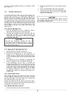
3.3 CHECKS
AND
ADJUSTMENTS
3.3.1
Purging the oil line
Open the bleed port screw and start the burner. Allow the oil to
drain into a container for at least 10 seconds. The oil should
flow absolutely free of white streaks or air bubbles to indicate
that no air is being drawn into the suction side of the oil piping
and pump. Slowly close and tighten the bleed screw.
Once closed, the flame will light up.
3.3.2 Pressure
adjustment
The oil pressure must be adjusted according to the
Technical Specifications of this manual. An adjustment
screw and a connection for a pressure gauge are located
on the oil pump for that purpose. Also refer to the burner
instruction manual.
3.3.3 Combustion
Check
IMPORTANT
The heat exchanger metal surfaces may have oil and the
baffle insulation also contains binders. These products will
burn or evaporate when the unit operates for the first time.
Because of this, the smoke reading may be inexact during
the first minutes of operation. Therefore, the unit must
operate during at least 60 minutes before taking any
readings to adjust the combustion quality. Let the unit cool
down before making any adjustments.
IMPORTANT
The combustion check verification MUST be performed
after the nozzle replacement or the burner cleaning. After
these manipulations, the combustion parameters are
necessarily modified. Refer also to the burner instruction
manual.
1.
Drill a test hole in the flue pipe, approximately 18
inches from the furnace breech. Insert the smoke test
probe into the hole. For installation using a sidewall
venting, use the orifice provided on the breech plate;
2.
From a cold start, let the unit operate for about 5
minutes;
3.
Set the burner air setting until you have between 0
and 1 on the Bacharach Scale (or a “trace”);
4.
Take a CO
2
sample at the same test location where
the #1 smoke reading was taken and make note of it.
Example: 13.8% of CO
2
or 2.5% of O
2
;
5.
Adjust the burner air setting to obtain a CO
2
reading
1.5% lower (or a O
2
reading 2.0% higher) than the
reading associated with the “trace” of smoke.
Example: 12.3% of CO
2
or 4.5% of O
2
;
6.
This method of adjusting the burner will result in clean
combustion (Bacharach smoke scale between 0 and
a trace) and ensure the proper functioning of the
system. The optimum CO
2
level is around 12% to
13% (or 3.5% to 5.0% of O
2
).
3.3.4
Draft Regulator adjustment
On chimney installations only, a barometric draft regulator
(supplied with the furnace) must be installed, in order to
ensure proper draft through the furnace. The barometric
damper must be mounted with the hinge pins in a
horizontal position and the face of the damper vertical for
proper functioning (see instructions included with the
damper.) After the furnace has been firing for at least five
Содержание OMF154L20A
Страница 18: ...18 Figure 9 Furnace Dimensions...
Страница 19: ...19 Figure 10 Wiring diagram 4 speed motor PSC...
Страница 20: ...20 Figure 11 Wiring diagram variable speed motor ECM...
Страница 21: ...21 Figure 12 Parts list with 4 speed motor PSC B500111A...
Страница 23: ...23 Figure 13 Parts list with variable speed motor ECM B50112A...


