3. Operate the unit to the flow rate mentioned in table
4. Installer can either use test mode (see table:16)
or t-stat fixed rate mode.
4. Adjustment or verification should be made on at
least two points, which are at flow rates 100% and
40%.
5. Note the manifold gas pressure.
6. To adjust the pressure, take off the regulator cap on
the gas valve and use a small slotted screwdriver in
the opening.
7. Only small variation in gas pressure should be
made by adjusting the pressure regulator (+/- 0.6
maximum)
8. Allow up to 20 seconds between each change to
the rotary dipswitch.
9. Once adjustment is made at 40% and 100% input,
turn off the power to the unit.
10. Turn the power back on, and verify pressure
adjustement.
11. Shut off the unit and replace the regulator cap.
12. Place the manifold pressure tap plug.
13. Check for leak.
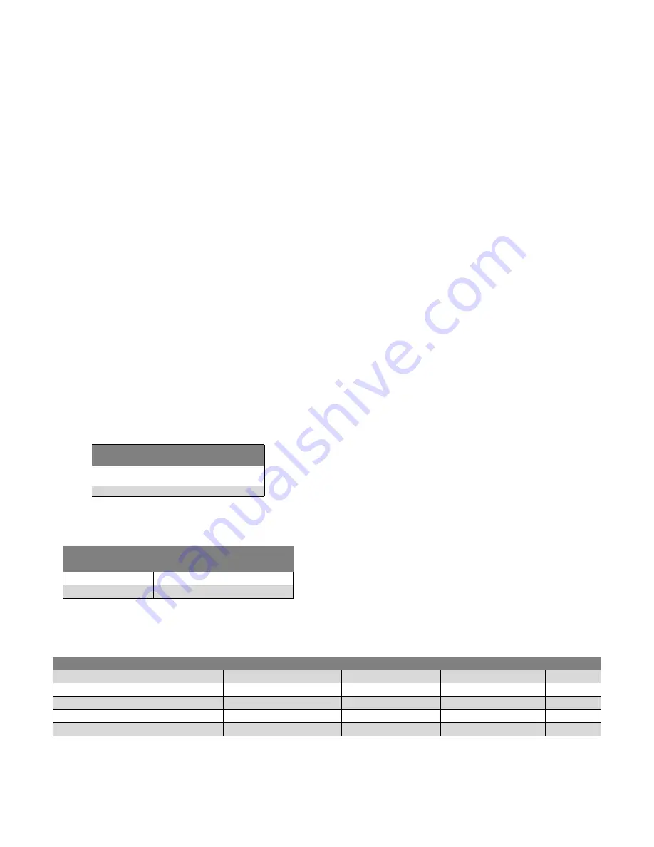
Table 3 – Inlet Gas Pressure
Gas Pressure in.w.c. (psig)
Minimum
Maximum
Natural
Gas
4.5
10.5
Propane 11.0
13.0
Table 4 – Outlet gas pressure
Gas Pressure in. w.c.
Input
Natural Gas
Propane
High fire (100%)
3.2 +/- 0.3
8.35 +/- 0.5
Low fire (40%)
0.8 +/- 0.3
2.09 +/- 0.3
6.3
PROPANE CONVERSION
To convert from natural gas to L.P. gas, installer should
use the appropriate conversion kit, in this case B40574-
03.
The conversion kit consist an orifice #56, jumper and
stickers to clearly identify conversion on the gas valve.
Follow the steps bellow to convert the gas valve to
propane :
1. Move the switch located on the valve to the «off»
position.
2. Remove the «NAT. GAS» label from the top of the
gas valve.
3. Using a pair of tweezers or needle nose pliers,
place the jumper (supplied) on the receptacle
located beneath the label that was removed in step
2.
Use care to make sure that both prongs of
receptacle engage the jumper.
4. Place the «LP» label (supplied with the kit) on the
gas valve over the opening to the jumper.
5. Attach the “WARNING” label (supplied with this kit)
to the gas valve where it can readily be seen.
6. Move the switch located on gas valve back to the
“ON” position.
7. Unscrew the manifold.
8. Replace the natural gas burner orifices with the LP
orifice (# 56) supplied with the kit.
9. Replace the manifold and make sure it’s properly
aligned with the burners.
10. Make sure the gas valve outlet pressure (measured
on the outlet pressure tap) is compliant with the
outlet pressure. Outlet pressure is specified in table
4 and on the nameplate of the furnace.
6.4
GAS PIPE GROMMET
For direct vent applications, the hole for the gas pipe on
the cabinet must be sealed to prevent air leakage. Install
the grommet in the hole, then insert the gas pipe.
Table 5 – Maximum capacity of pipe Cu.ft./Hr for pipe length ft (m)
Nominal Iron pipe size in. (mm)
Internal dia. in. (mm)
10 (3.0)
20 (6.0)
30 (9.1)
40 (12.1)
50 (15.2)
1/2 (13)
0.622 (158)
175
120
97
82
73
3/4(19)
0.824 (20.9)
360
250
200
170
151
1 (25)
1.049 (26.6)
680
465
375
320
285
1-1/4 (32)
1.380 (35.0)
1400
950
770
660
580
1-1/2 (39)
1.610 (40.9)
2100
1460
1180
990
900
15
Содержание CC15-M-V
Страница 18: ...Figure 17 Wiring Diagram 18...
Страница 23: ...Figure 25 Direct vent clearance 23...
Страница 24: ...Figure 26 Other than Direct vent clearance 24...
Страница 34: ...12 PART LIST Figure 27 Exploded view...
Страница 35: ...Figure 28 Exploded view continued...
Страница 36: ...Table 19 Part list Chinook Compact...
Страница 37: ...Table 20 Part list continued...
Страница 38: ...13 NOTES 38...
Страница 39: ...39...
Страница 40: ...40...


