


When 3" pipe is used, connect a 2" to 3" coupling to the 2" pipe.
For proper installation of venting/exhaust pipe:
1. Position the supplied venting gasket on the top panel
exhaust.
2. Slowly slide a 2" diameter pipe throught the venting
gasket. This step will be easier if pipe is chamfered.
3. Position this venting pipe length on the rubber vent
collector and tighten the collar.
4. Install the remaining vent pipes. It is recommended that
all pipes be cut, prepared, and preassembled before
permanently cementing any joint.
5. Working from furnace to outside, cut the pipe to the
required length(s).
6. Deburr the inside and outside of the pipe.
7. Chamfer the outside edge of pipe for better distribution of
primer and cement.
8. Clean and dry all surfaces to be joined.
9. Check dry fit of the pipe and mark insertion depth on the
pipe.
10. After the pipes have been cut and preassembled, apply a
generous layer of cement primer to the pipe fitting socket
and end of the pipe to insertion mark. Quickly apply
approved cement to end of the pipe and fitting socket
(over primer). Apply cement in a light, uniform coat on
the inside of socket to prevent build-up of excess cement.
Apply second coat.
11. While cement is still wet, twist pipe into the socket with
1/4” turn. Be sure the pipe is fully inserted into the fitting
socket.
12. Wipe excess cement from the joint. A continuous bead
of cement will be visible around perimeter of a properly
made joint.
13. Handle pipe joints carefully until cement sets.
14. Horizontal portions of the venting system shall be
supported to prevent sagging. Support any piping at a
minimum of every 5 ft. using perforated metal hanging
strap or commercially available hangars designed to
support plastic pipe.
15. Prevent condensate from accumulating in the pipes
by sloping the combustion air piping and vent piping
downward toward furnace a minimum of 1/4” per linear
ft. with no sags between hangers.
16. Complete the vent installation by installing the required
termination. See figures 23 to 27 for allowed termination.
17. Use appropriate methods to seal the openings where
combustion air pipe and vent pipe pass through roof or
sidewall.
7.8
COMBUSTION AIR PIPE
CONNECTION
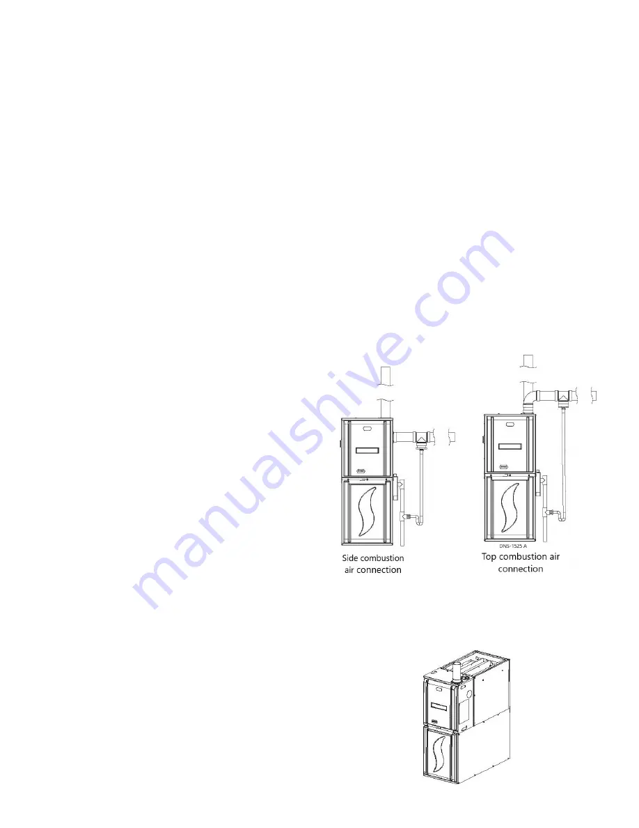
Chinook gas furnaces have three possible locations for the
combustion air connection : top panel, right side panel or left
side panel. Choose which configuration is best suited for your
application. See figures 19 and 20.
To connect the combustion air pipe, use the venting flange with
the gasket and screw it to the chosen location. Secure the
combustion air pipe to the flange using glue.
At the combustion air termination, use a 90° elbow or two
medium-radius sweep elbows to keep the inlet downward and
prevent the entry of rain. The inlet opening of the combustion
air termination must be a minimum of 12” above the anticipated
level of snow accumulation.
The furnace may have a drain tee assembly and trap installed
in the combustion air pipe as close to the furnace as possible
(see figure 18). This is to drain any water that may enter the
combustion air pipe, preventing entry in the furnace vestibule
area.
Note that with horizontal combustion air pipe there is a risk
of excessive moisture entering the combustion air pipe and
consequently, furnace cabinet. A moiture trap should be added
to the combustion air pipe as shown in figure 18.
Figure 18 – Combustion air moisture trap
Figure 19 – Top panel combustion air
20
Содержание C105-2-V
Страница 24: ...Figure 29 Direct vent clearance 23 ...
Страница 25: ...Figure 30 Other than Direct vent clearance 24 ...
Страница 32: ...Figure 31 Dimensions 31 ...
Страница 33: ...Figure 32 Two Stage ECM Wiring diagram 32 ...
Страница 36: ...Figure 33 Exploded view Cxx 2 V part 1 35 ...
Страница 37: ...Figure 34 Exploded view Cxx 2 V part 2 36 ...


