4.3.2
Side return
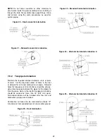
Remove 4 knock-outs on the side of the furnace of the
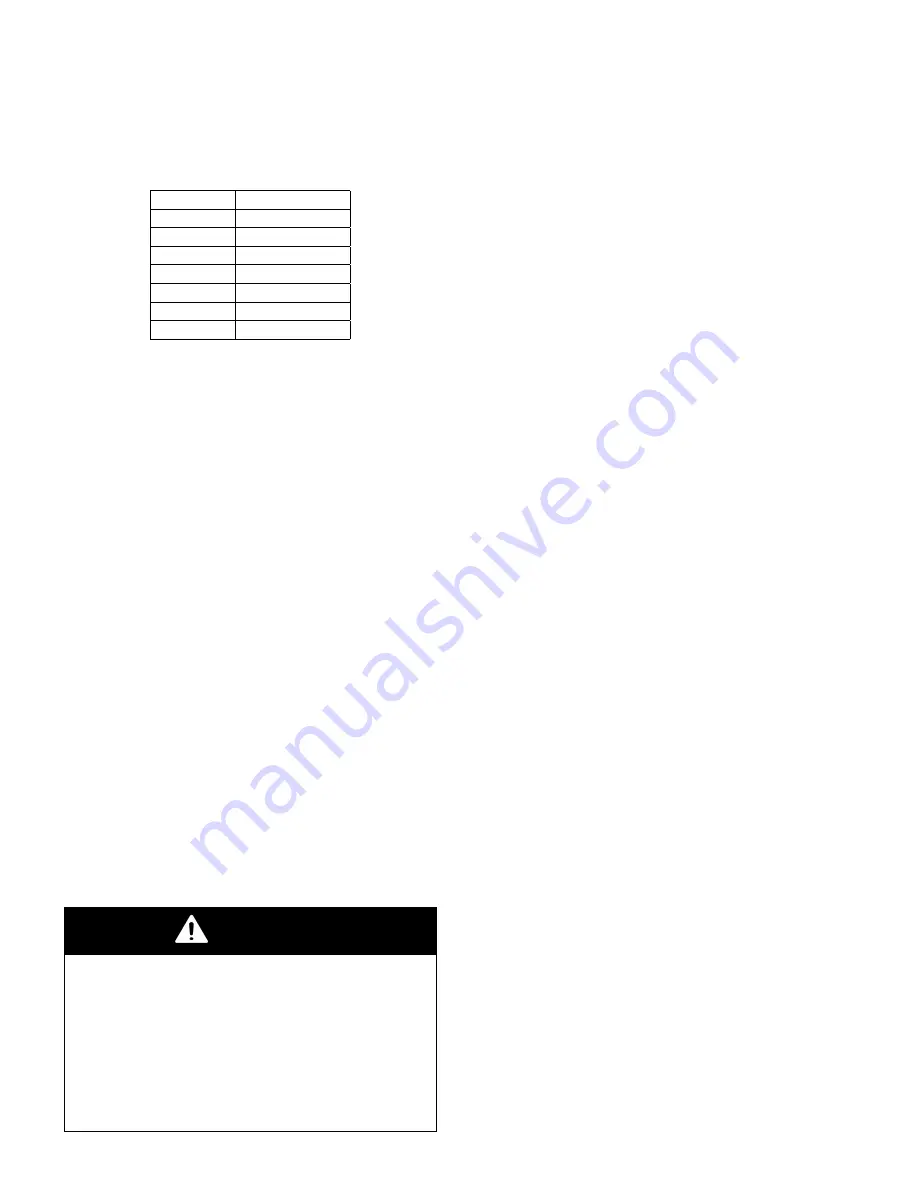
8 knock-outs available. Use table 3 for suggested return
size. Install the return air inlet as per local codes.
Table 3 – Suggested Filter size
Model
Filter size
15kBTU
16.00 x 20.00"
30kBTU
16.00 x 20.00"
45kBTU
16.00 x 20.00"
60kBTU
16.00 x 25.00"
75 kBTU
16.00 x 25.00"
105 kBTU
16.00 x 25.00"
120 kBTU
16.00 x 25.00"
4.4
SUPPLY AIR DUCTS
The supply air duct must be connected to the furnace
supply outlet air duct flanges.
DO NOT cut furnace
casing to attach supply air duct, humidifier, or other
accessories. All accessories must be connected to the
supply or return ductwork, external to furnace’s casing.
It is recommend that the outlet duct be provided with
a removable access panel.
This opening shall be
accessible when the furnace is installed and shall be
sized to allow the heat exchanger to be viewed or a probe
to be inserted for sampling the air stream. The cover
attachement should prevent leaks.
4.4.1
Ductwork acoutiscal treatment
Metal duct systems that do not have a 90 degree elbow
and 10 ft.
(3 M) of main duct to the first branch
take-off may require internal acoustical lining.
As an
alternative, fibrous ductwork may be used if constructed
and installed in accordance with the latest edition of
SMACNA construction standard on fibrous glass ducts.
Both acoustical lining and fibrous ductwork shall comply
with NFPA 90B as tested by UL Standard 181 for Class 1
Rigid air ducts.
5
GAS SUPPLY AND PIPING
5.1
GENERAL
WARNING
FIRE OR EXPLOSION HAZARD
Failure to follow the safety warnigns exactly could
result in serious injury, death or property damage.
Never test for gas leaks with an open flame.
Use a commercially available soap solution made
specifically for the detection of leaks to check
all connections. A fire or explosion may result
causing property damage, personal injury or loss
of life.
Gas piping must be installed in accordance with national
and local codes. Refer to current edition of NFGC in the
U.S.A.
Refer to current edition of CAN/CSA B149.1 in Canada.
Installations must be made in accordance with all
authorities having jurisdiction.
Use a back-up wrench on the inlet of the gas valve when
connecting the gas line to the gas valve.
Report to Table 6 for recommended gas pipe sizing.
Support all gas piping with appropriate straps and
hangers. Use a minimum of 1 hanger every 6 ft (1.8 m).
Joint compound (pipe dope) should be applied sparingly
and only to male threads of joints. Pipe dope must be
resistant to the action of propane gas.
An accessible manual equipment shut off valve MUST
be installed external to furnace casing.
Install a sediment trap in riser leading to furnace as
shown in Figure 16 Typical gas pipe arrangement.
Connect a capped nipple into lower end of tee. Capped
nipple should extend below level of furnace gas controls.
Install a union between the manual shut off gas and the
gas valve in order to remove it easily.
Piping should be pressure and leak tested in accordance
with the current edition of the NFGC in the United States,
local, and national plumbing and gas codes before the
furnace has been connected. Refer to current edition of
NSCNGPIC in Canada.
The gas supply pressure shall be within the maximum
and minimum inlet supply pressures marked on the rating
plate and in Table 4.
The furnace gas valve inlet pressure tap connection is
suitable to use as test gauge connexion providing test
pressure.
5.2
PROPANE CONVERSION
To convert from natural to L.P. gas, installer should use
the appropriate conversion kit. Please refer to parts lists
in this manual.
Make sure the inlet gas pressure is as indicated in table
4.
The conversion kit consist of orifices, spring and stickers
to clearly identify conversion on the gas valve.
5.3
GAS PIPE GROMMET
For direct vent applications, the hole for the gas pipe on
the cabinet must be sealed to prevent air leakage. Install
the grommet in the hole, then insert the gas pipe.
5.4
SETTING GAS OUTLET
PRESSURE
NOTE : These furnace are high altitude certified,
elevations under 4500 ft doesn’t require orifice
change.
14
Содержание C105-1-D
Страница 24: ...Figure 26 Alternate horizontal termination C Figure 27 Venting gasket 23...
Страница 25: ...Figure 28 Direct vent clearance 24...
Страница 26: ...Figure 29 Other than Direct vent clearance 25...
Страница 34: ...Figure 32 Single Stage PSC Wiring diagram...
Страница 35: ...Figure 33 Two Stage PSC Wiring diagram...
Страница 36: ...Figure 34 Single Stage ECM Wiring diagram...
Страница 39: ...Figure 35 Dimensions 38...
Страница 40: ...Figure 36 Exploded view CXX 1 X part 1...
Страница 41: ...Figure 37 Exploded view CXX 1 X part 2...
Страница 43: ...Figure 38 Exploded view Cxx 1 D part 1...
Страница 44: ...Figure 39 Exploded view Cxx 1 D part 2...
Страница 46: ...Figure 40 Exploded view Cxx 2 D part 1...
Страница 47: ...Figure 41 Exploded view Cxx 2 D part 2...


