


CALIBRATION LOG
Each time the sensor attached to the DCU is calibrat-
ed, the zero and span levels as well as the time and
date of the calibration are recorded. The initial cali-
bration is kept for the life of the sensor, and all subse-
quent calibrations are stored in a seven record FIFO
format. When the sensor is replaced, the calibration
log is cleared by pressing the “sensor replacement
switch” on the communication module in the DCU and
performing a successful calibration of the sensor.
Det-Tronics EagleVision™ software compares the ini-
tial calibration to later ones to produce a “sensor sen-
sitivity trend,” which can be a valuable maintenance
or troubleshooting tool. Refer to the Eagle Quantum
system manual, form number 95-8470, for complete
instructions regarding calibration.
FAULT TOLERANT NETWORK
The DCU utilizes a unique patented fault isolation
technique for detecting and isolating a wide variety of
network wiring problems. Using a combination of on-
board software and hardware, the module can deter-
mine when network integrity has been compromised.
Corrective action is taken by electrically disconnect-
ing the faulty segment of network wiring and properly
terminating the “good” side of the network. This auto-
matic “reconfiguration” changes the topology of the
network from a ring that starts and ends at the gate-
way to a linear bus network that is properly terminated
on either side of the isolated faulty network segment.
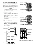
The DCU communicates with the LCU over the digital
highway as shown in Figure 2. In the event of a single
open or short circuit on the digital highway, all units
will be fully functional (condition A). In the event of
multiple open or short circuits on the digital highway,
all units except those between the two faults will be
able to communicate with the gateway (condition B).
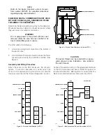
ADDRESSABILITY
Each device on the LON/SLC must be assigned a
unique address. This is accomplished by setting DIP
switches on the module’s circuit board. See Figure 3.
Each rocker switch has a specific binary value. The
node address is equal to the added value of all closed
rocker switches. All open switches are ignored. The
valid address range is from 5 to 250. Refer to the
Eagle Quantum system manual (form 95-8470) for
additional information.
REED SWITCH
A magnetic reed switch, located on the terminal
board, enables calibration of the sensor without open-
ing the enclosure. The switch is activated by placing
a magnet on a specified location on the side of the
enclosure.
INSTALLATION
The detectors are wired on a digital communication
loop starting and ending at the gateway, using com-
munication grade shielded twisted pair wire. Wiring
for power, inputs and outputs must be 18 AWG mini-
mum.
3
90-1118
LCU
B1544
CONDITION A
(OPEN OR SHORT)
CONDITION B
(OPEN OR SHORT)
Figure 2—Communication by means of the Digital Highway
1
2
3
4
5
6
7
8
1
2
3
4
1
2
4
8
16 32 64 128
OPEN
OPEN
}
LEAVE IN
OPEN POSITION
NODE ADDRESS EQUALS THE ADDED VALUE
OF ALL CLOSED ROCKER SWITCHES
A1557
BINARY
VALUE
CLOSED = ON
OPEN = OFF
Figure 3—Field Device Address Switches


