


Definition
Value
Description
Surface Industry
II
Equipment group
High level of protection
2
Equipment category
Group II
– zone 1 (gas)
– zone 2 (gas)
– zone 21 (dust)
– zone 22 (dust)
Atmosphere containing Gas, Va-
pors or Mist
G
Atmosphere
Atmosphere containing Dust
D
Constructional safety
c
Safety design
Hydrogene/ Acetylene
IIC
Gas group
T1
= 450°C
T2
= 300°C
T3
=
200°C
T4
= 135°C
T5
= 100°C
T6
= 85°C
Max surface temperat-
ure in
Gas
atmo-
sphere
Example temperatures: T85°C
T110°C T120°C T125°C T240°C
Max surface temperat-
ure in
Dust
atmo-
sphere
Ex Classification
If the motor is part of an assembly where the components have
different Ex classification, the component with the lowest level of
safety defines the Ex classification of the whole assembly.
Explosion prevention guidelines
In addition to the product instructions for air motors, the following
guidelines apply to explosion protected air motors.
Temperatures
– The maximum surrounding temperature for which the certific-
ation is valid is 40°C.
– 40°C is also the maximum allowed temperature of the com-
pressed air when it enters the motor.
– If the motor is installed in a equipment, the entire equipment
has to correspond to the guidelines 94/9/EC.
– Make sure that the compressed air fulfil our quality demands
(quality classes 2.4.3. and 3.4.4 respectively 3.5.4 acc. to
ISO/DIS 8573-1).
– Do not exceed maximum pressure of 6.3 bar, or as stated on
the motor nameplate. Exceeding the operating pressure can
increase the surface temperature due to higher rotating speed
and the motor can become an ignition source.
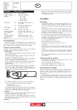
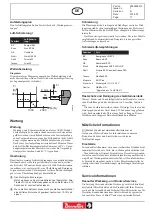
–
s016536
The following hotspots on the motor (as seen in the figure
above) can reach high temperatures during operation:
– motor housing
– seal ring at the output shaft
The highest temperatures occur when the motor is running at
full pressure without load. With increasing torque, the air motor
reduces the rotational speed and the temperature.
Cleanliness
– Make sure the motor is kept clean from dust and dirt to prevent
increased bearing and surface temperature.
– Make sure a silencer with a filtering effect at the air outlet is
installed to prevent any friction-heated particles entering into
the surrounding atmosphere.
Shaft load
– Make sure that the maximum shaft load stated in the section
Installation is not exceed, to prevent an excessive increaseof
the bearing temperature.
Installation
Air quality
– For optimum performance and maximum machine life we re-
commend use of compressed air with a maximum dew point
of +10°C. Installation of a refrigeration-type air dryer is recom-
mended.
– Use a separate air filter to remove solid particles larger than
30 microns and more than 90 % of water, installed as close as
possible to the machine and prior to any other air preparation
unit. Blow out the hose before connecting.
– The compressed air must contain a small quantity of oil. We
strongly recommend that you install a oil-fog lubricator. This
should be set according to air consumption by the air line tool
according to the following formula:
L
= Air consumption (litre/s).
(May be found in our sales literature).
D
= Number of drops per min (1 drop = 15 mm
3
)
L* 0.2 = D
this applies to the use of long work cycle air line tools. A single
point lubricator can also be used for tools with short running
cycles.
– For lubrication free motors it is an advantage if the compressed
air contains a small quantity of oil supplied from a fog lubric-
ator.
For further information please see Air Line Accessories in our
main catalogue.
Compressed air connection
– The machine is designed for a working pressure (e) of 6–7 bar
= 600–700 kPa = 87–102 psi.
– Blow out the hose before connecting.
– Recommended inlet hose size is 8 mm (5/16'').
– Recommended outlethose size is 10 mm (3/8'').
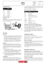
Connecting the air supply
When the compressed air supply is connected to the inlet, the dir-
ection of rotation will be as shown in the figure below. If the ex-
haust air is to be piped away, a hose should be connected to the
exhaust outlet.
The compressed air supply should be connected to the inlet that
gives the desired direction of rotation, see figure below. The inlet
tha is not in use functions as an additional outlet and must not be
plugged.
EN
2050538313
1
B
Part no
Issue no
Series no
2014-07
Date
4
Page
Содержание 205 148 132 4
Страница 123: ...6 3 90 psig s011050 WARNING ATEX 94 9 ATEX 2050538313 Part no BG 1 B Issue no Series no 2014 07 Date 123 Page...
Страница 157: ...A JP...
Страница 158: ...s011050 WARNING JP...
Страница 159: ...s016536 Fa N 1000 1000 2000 Fr N 8000346 Fr Fa 9 mm A JP...
Страница 160: ...A C JP...
Страница 161: ...1 2 3 4 5 6 7 8 JP...
Страница 166: ...H w t U S S Z U KO YW W Z_ZXZ X i w p z YWX TW k X w...
Страница 173: ......
Страница 174: ......
Страница 175: ......


