DESCO WEST
- 3651 Walnut Avenue, Chino, CA 91710 • (909) 627-8178
DESCO EAST
- One Colgate Way, Canton, MA 02021-1407 • (781) 821-8370 • Website:
TB-3031
Page 2 of 8
© 2014 DESCO INDUSTRIES, INC.
Employee Owned
Maintenance
“All ionization devices will require periodic maintenance for
proper operation. Maintenance intervals for ionizers vary
widely depending on the type of ionization equipment and
use environment. Critical clean room uses will generally
require more frequent attention. It is important to set-up
a routine schedule for ionizer service. Routine service is
typically required to meet quality audit requirements.” (ESD
Handbook TR20.20 section 5.3.6.7 Maintenance / Cleaning)
EIA-625, recommends checking ionizers every 6 months, but
this may not be suitable for many programs particularly since
an out-of-balance may exist for months before it is checked
again. ANSI/ESD S20.20 section 6.1.3.1 Compliance
Verification Plan Requirement states: “Test equipment shall
be selected to make measurements of appropriate properties
of the technical requirements that are incorporated into the
ESD program plan.”
CLEANING THE EMITTER POINTS
Under normal conditions, the ionizer will attract dirt and dust
(especially on the emitter points). To maintain optimum
neutralization efficiency and operation, cleaning should be
performed on a regular basis.
In the event of circuit failure, the unit will enter shutdown
mode.
When the unit enters shutdown mode, ionization will be
stopped, the LED on the front of the unit will illuminate a
constant red, and the audible alarm will continuously sound.
The user must then reset the unit by turning it OFF and back
ON.
The emitter points should be cleaned using the included
Emitter Point Cleaners or a swab dampened with Isopropyl
alcohol.
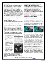
1. Turn the unit OFF and unplug the power cord.
2. Open the top screen by
loosening the screw and
swinging the grill to one
side.
3. Clean the emitter points
using the included Emitter
Point Cleaners or a swab
dampened with Isopropyl
alcohol.
4. Reattach the top screen.
5. Plug in the power cord
and turn the unit ON.
6. Verify the performance of
the ionizer by using a
charged plate monitor, or
ionization test kit.
With normal handling, the emitter points should not require
replacement during the life of the unit. If necessary,
item
Replacement Emitter Points are available for
purchase.
Adjustments and Compliance Verification
BALANCE OFFSET VOLTAGE ADJUSTMENT
The Chargebuster® Overhead Ionizer is an auto-balancing
unit. However, tuning or manual adjustment can be
accomplished by inserting a small screwdriver or trimmer
adjustment tool into the balance adjustment hole. To
increase the output in a positive direction, turn the
potentiometer clockwise. To increase the output in a
negative direction, turn the potentiometer counter-clockwise.
INPUT VOLTAGE CONFIGURATION
WARNING - Risk of electric shock
These servicing instructions are for use by qualified
personnel only. Do not perform any servicing of internal
parts unless you are qualified to do so.
NOTE: The AC power cord MUST always be disconnected
before the unit is disassembled.
The input voltage may be verified or reset by opening the
ionizer’s enclosure. This can be accomplished by removing
the 10 screws that secure the cover to the base.
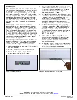
The ionizer’s input voltage can be configured to 120 VAC or
220 VAC using the JH1 jumpers located on its PCB. See
Figures 3 and 4 for these configurations.
Figure 3. 120 VAC jumper
setting
Figure 4. 220 VAC jumper
setting
If the supply voltage drops from 110 Volts to below 85 Volts
or from 200 Volts to below 170 Volts, the unit will shut down,
the audible alarm will beep and the LED will blink red. The
unit will automatically reset when the minimum voltage is
restored.
Auto-balancing closed-loop feedback technology can save
money and extend the maintenance interval of the ionizer.
What the sensor detects is that the offset voltage (balance)
has shifted and the circuits will attempt to compensate. In
the case of corona ionizers, one of the reasons for a shift in
offset voltage is frequently the particle buildup, commonly
called a “fuzz ball”, observed on the emitter points.
Compliance Verification should be per ESD TR53. Offset
voltage (balance) and both polarity’s discharge time should
be checked on every ionizer periodically using an Ionization
Test Kit or a Charged Plate Analyzer. Measure offset
voltage (balance) and both polarity’s discharge times. Clean
the emitter points (with electrical power off), adjust offset
voltage (balance) to zero and then re-test for offset voltage
(balance) and discharge times recording the measurements.


