

TB-3043
Page 5 of 6
© 2019 DESCO INDUSTRIES INC
Employee Owned
DESCO WEST
- 3651 Walnut Avenue, Chino, CA 91710 • (909) 627-8178
DESCO EAST
- One Colgate Way, Canton, MA 02021-1407 • (781) 821-8370 • Website:
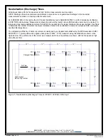
TP1
+16.0
-25.0
12"
12"
12"
12"
12"
TP4
+9.5
-12.0
TP7
+11.5
-15.0
TP10
+15.5
-21.0
TP2
+1.3
-1.8
TP5
+3.0
-4.1
TP8
+5.0
-6.5
TP11
+7.0
-10.0
TP3
+38.0
-59.0
TP6
+11.0
-16.0
TP9
+10.0
-12.5
TP12
+11.0
-14.0
High Output
Bench Top Ionizer
Air Flow
Charged Plate
12"
Figure 6. Neutralization (Discharge) Times at 100VAC, 50Hz input
Calibration
On a regular interval, most users will clean emitter pins and
calibrate the ionizer. Per ESD TR 53 section 5.3.6.7.1 “The
best practice is to measure the offset voltage and discharge
times, clean the unit, including emitter points and air filters
if present, offset voltage to zero (if adjustable), and then
repeat offset voltage and discharge time testing. If the unit
does not meet offset voltage specifications or minimum
established discharge time limits, further service is indicated.
Manufacturers should provide details on service procedures
and typical service intervals.”
Most companies will assign a number or otherwise
identify each ionizer and setup a compliance Verification /
Maintenance / Calibration schedule. If the ionizers all test
good, the data can justify lengthening the calibration period.
If ionizers require adjustment, the calibration period should
be shortened. Although ESD TR53 does not advise a test
frequency, JESDD625-A (Revision of EIA-625) recommends
ionizers be tested semiannually, noting to use “S3.1 except
the number of measurement points and locations may be
selected based on the application.”
NOTE: A charged plate analyzer or monitor should be
used in order to properly calibrate the Desco High Output
Benchtop Ionizer. EMIT offers the
Analyzer.
1. Properly setup the ionizer as described in the installation
procedure.
2. Turn the unit ON and set the fan speed to High.
3. Position the charged plate analyzer 12 inches directly in
front of the ionizer.
4. The balance (offset voltage) should be within 0 and ±2
volts. To increase the output in a positive direction, turn
the Balance potentiometer in a clockwise direction. To
increase the output in a negative direction, turn the
Balance potentiometer in a counter-clockwise direction.
5. Test the neutralization (discharge) time by applying a
±1,000 volt charge on the charged plate analyzer. The
neutralization (discharge) time should be less than 2
seconds. See figures 5 and 6 for typical discharge times.
The required limit per ANSI/ESD S20.20 is “user defined”.
6. Test the ionizer’s alarm by shorting its two fan grills
located on the front (see Figure 7). The alarm should
sound, and the STATUS LED should illuminate red.


