


DESCO WEST
- 3651 Walnut Avenue, Chino, CA 91710 • (909) 627-8178
DESCO EAST
- One Colgate Way, Canton, MA 02021-1407 • (781) 821-8370 • Website:
Desco.com
TB-3078
Page 2 of 6
© 2019 DESCO INDUSTRIES INC
Employee Owned
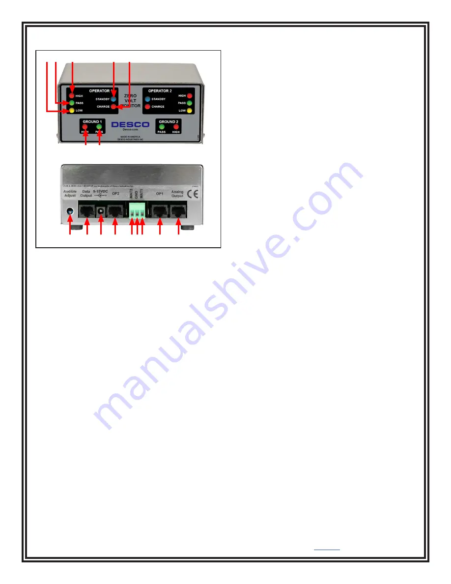
Features and Components
L. Mat 2 Terminal:
Monitors worksurface mat 2.
Connect the black mat monitor cord here.
M. Monitor Ground Terminal:
Common ground point
for the monitor. Connect the green monitor ground cord
here.
N. Mat 1 Terminal:
Monitors worksurface mat 1.
Connect the white mat monitor cord here.
O. Operator 1 Remote Jack:
Connect the white
operator remote cable here.
P. Analog Output:
For manufacturer use only.
Installation
1. Determine the mounting location of the Zero Volt
Monitor. The front panel should be visible to both
operators.
2. Determine the mounting locations of the operator
remotes. Be sure to install the remotes at a distance
that enables its leads to reach the back of the
monitor.
3. Install tinned wire ends of the mat cords to their
appropriate screw terminal block located at the back
of the monitor.
4. Attach the worksurface mats to ground using the
green mat ground cords. Install the ring terminal end
of the cord to an appropriate ground point. Attach
the snap terminals to the snaps on the worksurface
mats.
5. Install the tinned wire end of the green monitor
ground cord to the ground terminal located at the
back of the monitor. Install its ring terminal to an
appropriate ground point. Be sure to use a different
ground point than the one used for the mats. The
face plate screw of a grounded AC wall outlet may
provide a convenient connection point.
6. Route the mat cords from the back of the monitor
to the snaps on worksurface mats. The white cord
is for worksurface mat #1. The black cord is for
worksurface mat #2.
7. Insert the operator remote cables into their
appropriate jacks located at the back of the monitor.
The white cable is for operator #1. The black cable
is for operator #2.
8. Connect the power adapter to the power jack
located at the back of the monitor. Plug the power
adapter into a proper AC power outlet. The monitor
is now powered.
A B
C
D
E
F G
H
I
J
K
LMN
O
P
Figure 2. Zero Volt Monitor features and components
A. Operator Fail Low LED:
Illuminates and audible
alarm sounds when the operator’s resistance is below
the test limit.
B. Operator Pass LED:
Illuminates when the operator
is properly grounded.
C. Operator Fail High LED:
Illuminates and audible
alarm sounds when the operator’s resistance is above
the test limit.
D. Operator Standby LED:
Illuminates when the
operator is not connected to the operator remote.
E. Operator Charge LED:
Illuminates and audible alarm
sounds when the operator's body voltage is greater than
±1.25 VDC.
F. Mat Fail LED:
Illuminates and audible alarm sounds
when the worksurface mat is not properly grounded.
G. Mat Pass LED:
Illuminates when the worksurface
mat is properly grounded.
H. Alarm Audible Adjustment:
Turn the trimpot
clockwise to increase the audible alarm volume. Turn
the trimpot counter-clockwise to decrease the audible
alarm volume.
I. Data Output:
For manufacturer use only.
J. Power Jack:
Connect the included 12 VDC power
adapter here.
K. Operator 2 Remote Jack:
Connect the black
operator remote cable here.


