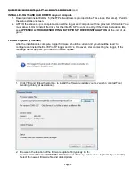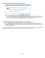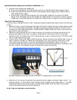
QUICK START GUIDE , ELITEpro SP™ and ELOG™ 14 SOFTWARE
(cont.)
4.
Send the Setup Table to the ElitePro SP.
a) Once your setup table is successfully saved, click on the "Send Setup Table to Logger" button.
b) Select Overwrite ACTIVE Table. ELOG 15 automatically initiates logging when a Setup Table is
downloaded to the Logger.
c)
At the prompt, select Continue Logging if you have already installed or are about to install the
logger. Note that logging will not occur unless its voltage leads are connected to a load or a power
transformer is used (see Appendix B, “ElitePro SP Power Source” on page 6 for more information).
ElitePro SP Field Installation
This step can be completed before or after creating and uploading the Setup Table covered in the previous
section.
1.
Make the voltage connections between the logger and load as needed using the voltage leads provided
(L1, L2, L3, and N). Note that typically, the logger is powered by voltage provided to L1 and L2 when
connected to the load being monitored. See Appendix B, "ElitePro SP power source" at the end of this
document for more information.
2.
Attach the current transducers (CTs) to the conductors of the load you are measuring. Orient the CT
properly with respect to the load. For clamp-on or flexible CTs, the arrow on the CT case points
towards the load. For split-core CTs with a removable leg, ensure the label that says “This Side Toward
Source” faces away from the load.
3.
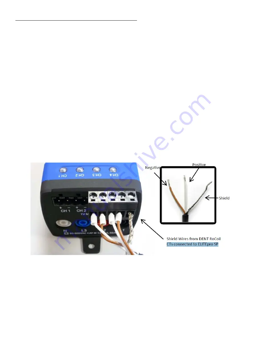
Connect the CT leads to the ElitePro SP Phoenix-style screw connectors. Note that the high (+) wire of
the CT (the white, banded, or numbered wire depending on CT type) should go to the left (+) screw
terminal of each channel input. If you are using Dent RoCoil (blue flexible coil) CTs, be sure to
connect the shield wires from all CTs to the shield terminal. This reduces interference and improves the
accuracy of the CT. See illustration below for typical Dent RoCoil connections.
Example showing two properly wired Dent RoCoil CT’s (voltage leads not yet installed)
4.
Attach the CTs to the load conductors that correspond to the voltage connections made in step 1. For
example, the CH1 CT must attach to the conductor whose voltage is being monitored by L1. A helpful
diagram illustrating wiring can be viewed in the ELOG setup table screen by clicking "View typical
setup" (see previous section for more information).
Verify Proper Configuration and Installation
Page 5


