


Chapter 2 Getting Started the BHT and System Menu
Defining the function of M1 , M2 , M3 (left-hand trigger switch), or M4 (right-hand trigger
switch) key
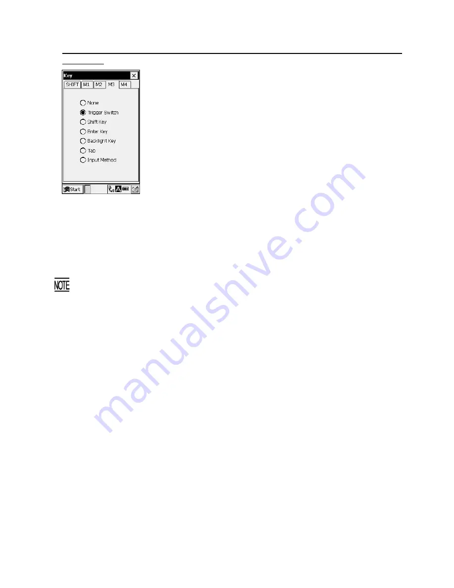
Tapping the
M1
,
M2
,
M3
, or
M4
tab displays the screen as shown at
left. (This example appears when the
M3
tab is chosen.)
The
M1
,
M2
,
M3
or
M4
key can function as listed below.
None:
The key entry will be ignored.
Trigger Switch:
As a trigger switch.
Shift Key:
As a
SF
key.
Enter Key:
As an
ENT
key.
Backlight Key:
As a backlight function on/off key.
Tab:
As a tab key.
Input Method:
As an alphabet entry switching key.
The
M1
and
M2
keys are assigned the tab key and alphabet entry switching function by default. You can
make those keys function as a trigger switch,
SF
key,
ENT
key, or backlight function on/off key.
If you define the
M4
key as the backlight function on/off key, pressing the
M4
key activates or deactivates
the backlight function.
The backlight function on/off key can be assigned only to any one of
M1
through
M4
keys. The key
defined more recently will act as the backlight function on/off key and one defined earlier will be
ignored.
That is, if you define the
M1
and
M2
keys as the backlight function on/off key in this sequence, the
M2
key will work as the backlight function on/off key and the
M1
key's entry will be ignored.
If none of the
M1
through
M4
keys are assigned a backlight function on/off key, the combination of
the
SF
and
M4
keys work as a backlight function on/off key by default.
67
Содержание BHT-100BW-CE
Страница 1: ...User s Manual Bar Code Handy Terminal BHT 100BW CE...
Страница 136: ......


