background image

Page 19

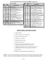
DIAPHRAGM PUMP PLUMBING PARTS LIST

REF.

PART

NO.

NO.

QTY

DESCRIPTION

NOTE:  Contact local authorized Briggs and Stratton dealer for replacement gas engines and parts.
Need model no. and type no. of engine to order parts from your Briggs and Stratton dealer.

REF.

PART

NO.

NO.

QTY

DESCRIPTION

1.

P55 23A

1

55 gallon Tank (incl. lid, agitation and
outlet fittings).

2.

PL5A

1

5î cover for tank

3.

5044 -1

1

Single Agitation Wand Assembly

4.

M1200

1

1/2" MPT Short Nipple

5.

EL1238

1

1/2" MPT x 3/8" Hose Barb Elbow

6.

580RB

-

5/8" I.D Rubber Hose

7.

UV075FP

3

3/4" Poly Ball Valve

8.

A3438

3

3/4" MPT x 3/8" Hose Barb

9.

B6H

10

3/8" Hose Clamp

10.

380RB

-

3/8" I.D Rubber Hose

11.

EL114 34

1

1-1/4" MPT x 3/4" Hose Barb Elbow

12.

BEL3434

3

3/4" MPT x 3/4" Hose Barb Elbow

13.

B12H

4

3/4" Hose Clamp

14.

340RB

-

3/4" I.D Rubber Hose

15.

BM3400

4

3/4" Short Nipple

-

RVF34 80

-

3/4" Line Strainer w/80 mesh screen

16.

RVF34C

1

3/4" Strainer Cup

17.

RVF34GV

1

Viton O-ring for 3/4" Strainer

18.

RVF380

1

80 Mesh Screen for 3/4" Strainer

19.

RVF34B

1

Strainer Bowl

20.

BTT34

2

3/4" FPT Tee

OPERATION INSTRUCTIONS

1.

Be sure oil is halfway up the clear oil sight tube.  If
necessary, fill to correct level with 30 weight non-
detergent motor oil.

2.

Make sure the suction hose barb is tightly screwed onto
the suction union, and that there are no air leaks on the
inlet side of the pump.

3.

Check the charge pressure on the pulsation damper
before starting the pump.  The pressure is checked with
a standard automotive air gauge.  The pressure should
be at approximately 20% of the maximum operating
pressure with a minimum charge of 10 PSI.

4.

Allow the pump to start under low pressure by removing
restrictions on the outlet of the pump.  The restriction on
the pump is removed by rotating the red knob on the
control unit so that the letter A on the knob is in the 12
o'clock position.

5.

Start pump and let run for approximately one minute at
low pressure.  Stop pump and check the oil level in sight
glass.  Add 30 weight non-detergent oil if necessary.

6.

Adjust pump to desired pressure by changing the relief
valve setting on the control unit, relief valve or unloader.
First back out relief valve adjustment knob to zero.  Then
rotate red bypass selector knob so that the letter C is in
the 12 o'clock position.  Adjust pressure by rotating relief
valve adjustment knob to desired pressure.

1.

After use, flush pump with clean water.

2.

Change oil and diaphragms every 500 hours.  To drain
oil from the pump, remove cap from oil sight tube, turn
pump upside down and rotate the shaft until oil stops
flowing out.  To fill pump with oil, slowly pour oil into sight
tube while turning the pump shaft.  Turning the pump
shaft purges all the air out of the crankcase.  Always
change oil when replacing diaphragms.

3.

For winter storage or if a freezing condition will be
encountered, flush pump with a 50/50 mixture of water
and antifreeze.

MAINTENANCE INSTRUCTIONS

Please order replacement parts by PART NO. and DESCRIPTION.

21.

A3458

1

3/4" MPT x 5/8" Hose Barb

22.

9910D19GRG

I

1

Diaphragm Pump w/Gear Reducer

23.

GE3HP

1

3.5 HP Gas Engine (Horizontal Shaft)

-

GH4HP

1

4 HP Gas Engine (Horizontal Shaft)

24.

00372

4

5/16"-18 UNC x 1-1/2" Hex Head Bolt

25.

02802

5

5/16"-18 UNC Nylon Insert Locknut

26.

05596

1

Tee Mount Bracket

27.

02772

4

1/4"-20 UNC Nylon Insert Locknuts

28.

6B1

1

Direct - o - Valve

29.

160GBF

1

160 lb. Brass Pressure Gauge

30.

04055

4

1/4"-20 UNC x 1" Hex Head Bolt

31.

00214

4

1/4" Flatwasher

32.

A1238

1

1/2" MPT x 3/8" Hose Barb Reducer

33.

EL3438

1

3/4" MPT x 3/8" Hose Barb Elbow

34.

05034

1

6B1 Valve Mounting Plate

35.

F3400

1

3/4" MPT Plug

36.

A1438

1

1/4" MGHT x 3/8" Hose Barb

37.

30L22425 18

1

Spray Wand

38. 5500 18PP 1

Adjustable Tip (ordered separate)

39.

B24H

2

1-1/4" Hose Clamp

40.

02990

1

.313 NC x 1 GR5 Hex bolt

41.

02801

1

Nut .313 NC Lock, Nylon Insert

Содержание 55 GALLON SKID MOUNT LAWN AND GARDEN SPRAYER

Страница 1: ... 4010 320th St P O Box 189 Boyden IA 51234 PH 712 725 2311 Toll Free 1 800 543 3626 FAX 1 800 845 6420 www demco products com ASSEMBLY CALIBRATION OPERATION REPLACEMENT PARTS READ complete manual CAREFULLY BEFORE attempting operation 12 04 AS20008 Rev 3 DOING OUR BEST TO PROVIDE YOU THE BEST ...

Страница 2: ...kdown and List 21 Truss T Boom Mounting Assembly Parts Breakdown and List 22 Spray Wand 30L22425 18 Parts Breakdown and List 23 Roller Pump C4101 Parts Breakdown and List 23 Electric Pump 8000 543 150 Parts Breakdown and List 23 Optional Electric Pump 2088 343 135 Parts Breakdown and List 23 Optional Electric Pump 10983 Parts Breakdown and List 24 Diaphragm Pump D19GR Parts Breakdown and List 25 B...

Страница 3: ...ou satisfied with the company s resolution of your problem Why did you purchase this product Please list the specific source of information prompting this purchase After purchasing this product do you see any needed product improvement If yes what improvement What other products would you like to see DEMCO offer Comments Owner s Name Mailing Address City State Zip Code Model Serial Purchase Date O...

Страница 4: ...Page 4 Postage Dethmers Manufacturing Company 4010 320th Street Box 189 Boyden Iowa 51234 ...

Страница 5: ...is to be limited to the most extreme situations typically for machine components which for functional purposes cannot be guarded WARNING Indicates a potentially hazardous situation that if not avoided could result in death or serious injury and includes hazards that are exposed when guards are removed It may also be used to alert against unsafe practices CAUTION Indicates a potentially hazardous s...

Страница 6: ... missing Location of such decals is indicated in this booklet Do not attempt to operate this sprayer under the influence of alcohol or drugs Review safety instructions with all users Operator should be a responsible adult DO NOT ALLOW PERSONS TO OPERATE OR ASSEMBLE THIS UNIT UNTIL THEY HAVE DEVELOPED A THOROUGH UNDERSTANDING OF SAFETY PRECAUTIONS AND HOW IT WORKS To prevent injury or death use a t...

Страница 7: ...ARENESS WARNING To prevent serious injury or death ï Refer to chemical supplier and manufacturer recommendations as well as all licensing restrictions or regulations ï Always wear recommended protective clothing when working with chemicals or sprayer ï Be sure to dispose of all unused chemicals or solutions in proper and ecologically sound manner Improper use can injure people animals plants and s...

Страница 8: ...ar protective clothing and substantial shoes It is recommended that suitable protective hearing and eye protection be worn The operator may come in contact with certain materials which may require specific safety equipment relative to handling of such materials Examples extremely dusty molds fungus bulk fertilizers etc Give sprayer a visual inspection for any loose bolts worn parts or cracked weld...

Страница 9: ... banks DO NOT operate on steep slopes as overturn may result Operate up and down not across intermediate slopes Avoid sudden starts and stops Pick the most level possible route when transporting across fields Avoid edges of ditches gullies and steep hillsides Be extra careful when working on inclines Periodically clear sprayer of brush twigs or other materials to prevent buildup of dry combustible...

Страница 10: ...g downhill Do not coast Do not drink and drive Comply with state and local laws governing highway safety and movement of farm machinery Use approved accessory lighting flags and necessary warning devices to protect operators of other vehicles on highway during transport Various safety lights and devices are available from your dealer Use of flashing amber lights is acceptable in most localities Ho...

Страница 11: ...hments Use a small piece of cardboard or wood Hydraulic fluid escaping under pressure can penetrate skin Openings in skin and minor cuts are susceptible to infection from hydraulic fluid Without immediate medical treatment serious infection and reactions can occur When disconnecting hydraulic lines shut off hydraulic supply and relieve all hydraulic pressure Replace all shields and guards after se...

Страница 12: ...0 400 540 7 8 170 230 420 570 650 880 1 225 300 630 850 970 1310 Torque figures indicated are valid for non greased or non oiled threads and heads unless otherwise specified Therefore do not grease or oil bolts or capscrews unless otherwise specified in this manual When using locking elements increase torque values by 5 GRADE or CLASS value for bolts and capscrews are identified by their head mark...

Страница 13: ...cket 7 04346 1 Left Hand Boom Mount 04348 1 Right Hand Boom Mount not shown 8 04347 2 Boom Mounting Arms 9 02645 2 23 Saddle 10 1 55 gal tank 11 00095 2 3 8 x 3 4 Square Head Set Screw 12 04352 4 5 16 18 UNC x 4 Hex Head Bolt 13 02802 4 5 16 18 UNC Nylon Insert Locknut 14 04342 1 Tank Top Mount 15 04344 1 Hand Wand Mount 16 04345 1 Valve Mount 17 05034 1 Valve Mount Plate 18 00059 6 3 8 Flatwasher...

Страница 14: ...WN for 12 BOOM to boom NOTE USE THREAD SEALANT ON ALL THREADED FITTINGS 1 2 3 4 5 6 7 6 8 11 10 12 12 13 13 13 13 14 12 12 15 15 15 12 12 16 10 10 10 17 18 19 20 23 24 25 21 28 29 30 22 33 32 31 15 12 35 37 36 26 38 39 12 43 10 10 16 41 40 40 42 9 15 44 27 B A 9 C D 6 6 6 34 45 ...

Страница 15: ...mbly 4 M1200 1 1 2 MPT Short Nipple 5 BEL1212 1 1 2 MPT x 1 2 Hose Barb Elbow 6 B6H 6 3 8 Hose Clamp 7 120RB 1 2 I D Rubber Hose 8 BEL3412 1 3 4 MPT x 1 2 Hose Barb Fitting 9 UV075FP 3 3 4 Poly Ball Valve 10 BM3400 6 3 4 Short Nipple 11 T34F 1 3 4 FPT x 3 4 Hose Barb Tee 12 B12H 8 3 4 Hose Clamp 13 340RB 3 4 I D Rubber Hose 14 EL114 34 1 1 1 4 MPT x 3 4 Hose Barb Elbow 15 BEL3434 5 3 4 MPT x 3 4 H...

Страница 16: ...o boom NOTE USE THREAD SEALANT ON ALL THREADED FITTINGS 1 2 3 4 5 6 7 6 8 11 10 12 12 13 13 13 13 14 12 12 15 15 15 12 12 16 10 10 10 17 18 19 20 23 24 25 21 28 29 30 22 33 32 31 15 12 35 37 36 40 39 41 12 43 12 12 13 26 42 41 42 9 15 44 38 B A 9 C D 6 6 6 34 27 6 41 13 39 45 ...

Страница 17: ...Hose Barb Tee 12 B12H 14 3 4 Hose Clamp 13 340RB 3 4 I D Rubber Hose 14 EL114 34 1 1 1 4 MPT x 3 4 Hose Barb Elbow 15 BEL3434 5 3 4 MPT x 3 4 Hose Barb Elbow 16 BTT34 1 3 4 FPT Tee RVF34 80 3 4 Line Strainer w 80 mesh screen 17 RVF34C 1 3 4 Strainer Cup 18 RVF34GV 1 Viton O ring for 3 4 Strainer 19 RVF380 1 80 Mesh Screen for 3 4 Strainer 20 RVF34B 1 StrainerBowl 21 C4101 1 RollerPump C4101GE 1 Ro...

Страница 18: ... 31 9 37 15 15 20 9 9 9 36 10 10 32 7 38 27 2 5 10 9 8 7 8 10 11 13 12 7 15 17 18 19 20 14 15 21 13 12 13 6 22 23 24 25 41 26 39 33 34 8 10 35 DIAPHRAGM PUMP PLUMBING PARTS BREAKDOWN NOTE USE THREAD SEALANT ON ALL THREADED FITTINGS 40 9 9 42 ...

Страница 19: ... A on the knob is in the 12 o clock position 5 Start pump and let run for approximately one minute at lowpressure Stoppumpandchecktheoillevelinsight glass Add 30 weight non detergent oil if necessary 6 Adjust pump to desired pressure by changing the relief valvesettingonthecontrolunit reliefvalveorunloader Firstbackoutreliefvalveadjustmentknobtozero Then rotate red bypass selector knob so that the...

Страница 20: ... 12 Volt Electric Pump 2088 343 135 12 Volt Electric 3gpm Pump 10983 1 12 Volt Electric 5gpm Pump 12 00336 4 1 4 20 UNC x 1 1 4 Hex Head Bolt 13 00214 4 1 4 Flatwasher 14 02772 7 1 4 20 UNC Nylon Insert Locknut 15 EL3812 1 3 8 MPT x 1 2 Hose Barb 16 BTT12G 1 1 2 FPT Tee Tapped for Gauge 17 60GB 1 60 lb Pressure Gauge 18 00955 1 1 4 20 UNC x 1 x 2 Round U bolt 19 M1238 1 1 2 MPT x 3 8 Reducer Nippl...

Страница 21: ...ment parts by PART NO and DESCRIPTION 1 2 3 4 4 3 5 5 7 8 10 11 12 13 6 15 16 1 16 16 17 17 18 19 25 26 20 24 27 16 21 22 23 6 28 9 16 18 1 1 2 2 2 2 4 5 6 6 6 6 7 8 3 3 3 3 REF PART NO NO QTY DESCRIPTION TRUSS T BOOM PARTS LIST 1 04347 2 Boom Mounting Brackets 2 00909 4 3 8 16 UNC x 1 3 8 Round U bolt 3 02678 4 Boom Mounting Plate 4 00059 8 3 8 Flatwasher 5 02592 8 3 8 16 UNC Nylon Insert Locknut...

Страница 22: ...nsion 25 7490BRTF Valve Seat Sub Assembly 26 5500 6PP Adjustable Tip ordered separately Not included with wand above AB30L Parts Kit includes all items with 30L 22425 18 SPRAY WAND PARTS BREAKDOWN Please order replacement parts by PART NO and DESCRIPTION C4101 ROLLER PUMP PARTS LIST Please order replacement parts by PART NO and DESCRIPTION 3 4 11 10 9 8 6 7 3 4 5 2 1 1 1800 0001 1 Bearing Retainer...

Страница 23: ...RT NO and DESCRIPTION ELECTRIC PUMP 8000 543 150 PARTS LIST 1 2 3 4 5 6 OPTIONAL 3 G P M ELECTRIC PUMP 2088 343 135 PARTS BREAKDOWN 6 5 2 1 4 3 REF PART NO NO DESCRIPTION 1 94 230 36 Switch Check valve and Upper Housing Kit 2 94 232 05 Valve Plate assembly 3 94 238 04 Diaphragm Drive assembly 4 94 370 03 Motor 5 94 231 30 Complete Pump Head assembly includes parts 1 2 3 Replaces all previous switc...

Страница 24: ...N OPT ELECTRIC PUMP 10983 PARTS LIST 4 1 4 7 8 1 120RB 1 2î I D Rubber Hose 2 11055 Valve Housing Assembly 3 11056 Lower Housing Assembly 4 B6H 3 8î Hose Clamp 5 11054 Upper Housing Assembly 6 RVB12 80 1 2 MPT x 1 2 Hose Barb Bowl Filter 7 BA1212 1 2 MPT x 3 8 Hose Barb 8 BEL1212 1 2 MPT x 1 2 Hose Barb Elbow 9 11984 Micro Switch Inside Case 9 ...

Страница 25: ...ng Pin 38 9910 800560 1 O ring 39 9910 800490 1 Positioning Rod 40 9910 800530 1 3 8 Outlet Hose Barb 41 9910 800670 1 5 8 Bypass Barb 42 9910 800680 1 Barb Nut 43 9910 770140 1 O ring 44 9910 800480 1 Indicator Scale 45 9910 800440 1 Relief Valve Seat Holder 46 9910 800450 1 Tension Spring 47 9910 800460 1 Relief Valve Plunger 48 9910 800470 1 Adjustment Cap Relief Valve 49 9910 480550 1 Retainer...

Страница 26: ...ng Viton 5 36307SS Washer Type 316 Stainless Steel 6 7717 2 209VI O ring Viton 7 36306SS Spring Type 316 Stainless Steel 8 36305 Stem Stainless Steel Polyethylene 9 36303PP Body Polypropylene 10 36309SS Retaining Clip Stainless Steel AB6B1 Spare Parts Kit includes items with Please order replacement parts by PART NO and DESCRIPTION 1 2 3 6 5 4 7 8 9 10 AA17I TEE VALVE PARTS LIST 1 8012 1 2SS 1 16 ...

Страница 27: ...and grommets to insure they are in good condition 4 CONTROLS Check for leakage plugging or wear on all valves fittings etc Clean off any build up of foreign material 5 PUMP Check to be sure pump turns freely 6 FRAME Be sure all bolts are tightened 7 REPLACEMENT PARTS Replace all worn or damaged parts After Season Care NOTE It is important that when cleaning sprayer you wearpropersafetyequipment Se...

Страница 28: ...Page 28 DETHMERS MFG COMPANY P O BOX 189 4010 320th St BOYDEN IA 51234 PH 712 725 2311 FAX 712 725 2380 TOLLFREE 1 800 54DEMCO 1 800 543 3626 www demco products com ...

Отзывы: