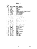
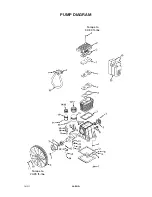
Delta OILLUBE AIR COMPRESSOR D25235 029-2 Скачать руководство пользователя страница 19

19-ENG

D25235

Air Compressor Pump Intake
and Exhaust Valves

Once a year have a Trained Service
Technician check the air compressor
pump intake and exhaust valves.

Inspect Air Lines and Fittings
for Leaks

1.

Turn air compressor off, lock out
the power supply, and relieve all
air pressure from the air tank.

2.

Apply a soap solution to all air
line fittings and connections/pip-
ing.

3.

Correct any leaks found.

IMPORTANT:

Even minor leaks can

cause the air compressor to over-
work, resulting in premature break-
down or inadequate performance.

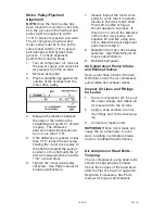
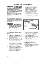
Motor Pulley/Flywheel
Alignment

NOTE:

Once the motor pulley has

been moved from its factory set loca-
tion, the grooves of the flywheel and
pulley must be aligned to within
1/16" to prevent excessive belt wear.
The air compressor flywheel and
motor pulley must be in-line (in the
same plane) within 1/16" to assure
belt retention within flywheel belt
grooves.  To check alignment, 
perform the following steps:
1.

Turn air compressor off, lock out
the power supply, and relieve all
air pressure from the air tank.

2.

Remove belt guard.

3.

Place a straightedge against the
outside of the flywheel and the
motor drive pulley.

4.  Measure the distance between

the edge of the belt and the
straightedge at points A1 and A2
in figure.  The difference
between measurements should
be no more than 1/16".

5.

If the difference is greater or less
than 1/16" loosen the set screw
holding the motor drive pulley to
the shaft and adjust the pulley’s
position on the shaft until the A1
and A2 measurements are within
1/16" of each other.

6.

Tighten the motor drive pulley
set screw.  See Parts manual for
torque specifications.

Air compressor Head Bolts -
Torquing 

The air compressor pump head bolts
should be kept properly torqued.
Check the torques of the head bolts
after the first five hours of operation.
Retighten if necessary. See Parts
manual for torque specifications.

7.  Visually inspect the motor drive

pulley to verify that it is perpen-
dicular to the drive motor shaft.
Points B1 and B2 of Figure
should appear to be equal.  If
they are not, loosen the setscrew
of the motor drive pulley and
equalize B1 and B2, using care
not to disturb the belt alignment
performed in step 2.

8.  Retighten the motor drive pulley

setscrew.  See Parts Manual for
torque specifications.

9.

Reinstall belt guard.

Содержание OILLUBE AIR COMPRESSOR D25235 029-2

Страница 1: ...elta Machinery To learn more about DELTA MACHINERY visit our website at www deltamachinery com For Parts Service Warranty or other Assistance please call 1 866 422 4286 Oillube Air Compressor with 2 S...

Страница 2: ...he symbols below Please read the manual and pay attention to these symbols IMPORTANT SAFETY INSTRUCTIONS Some dust created by power sanding sawing grinding drilling and other construction activities c...

Страница 3: ...rop erty damage To reduce the risk of fire do not allow the compressor to operate unattended Always operate the compressor in a well ventilated area free of combustible materials gasoline or solvent v...

Страница 4: ...r 1 Failure to properly drain con densed water from tank causing rust and thinning of the steel tank 2 Modifications or attempted repairs to the tank 3 Unauthorized modifications to the unloader valve...

Страница 5: ...he compressor is connected provides proper electrical grounding correct voltage and adequate fuse pro tection The compressed air directly from your compressor is not safe for breathing The air stream...

Страница 6: ...t can cause serious injury if they com into contact with you or your cloth ing HOW TO PREVENT IT WHAT CAN HAPPEN WARNING RISK OF FALLING A portable compressor can fall from a table workbench or roof c...

Страница 7: ...n or unauthorized parts HOW TO PREVENT IT WHAT CAN HAPPEN WARNING RISK OF UNSAFE OPERATION Unsafe operation of your air compressor could lead to serious injury or death to you or others HAZARD HOW TO...

Страница 8: ...a 50 duty cycle This means an air compressor that pumps air more than 50 of one automatically The low pressure at which the motor automatically restarts is called cut in pressure Cut Out Pressure Whe...

Страница 9: ...air compressor will have a tendency to tip 2 Remove and discard the 4 screws and washers holding the compressor to the pallet 3 With the help of another person carefully remove air compressor from pa...

Страница 10: ...on The compressor must be properly mounted The air compressor MUST be bolted to a solid level surface Hardware needed 4 Concrete anchors not sup plied 4 3 8 Lag screw to fit con crete anchors not supp...

Страница 11: ...RISK OF ELECTRI CAL SHOCK Improper electrical grounding can result in electrical shock The wiring should be done by a quali fied electrician to comply with national and local electrical codes A quali...

Страница 12: ...valve is not sup plied with this unit You must purch sase the shut off valve separately A separate regulator is recom mended to control the air pres sure Air pressure from the air tank is usually too...

Страница 13: ...r discharge valve Turn knob counter clockwise to open and clockwise to close Regulator sold separately not shown An air pressure regulator or a sepa rate air transformer which combines the functions o...

Страница 14: ...Intake Filter not shown This filter is designed to clean air coming into the pump This filter must always be clean and ventilation openings free from obstructions See Maintenance Before Starting Break...

Страница 15: ...FF 2 Close the globe valve 3 Attach hose and accessories NOTE A regulator MUST be installed when using accessories rated at less than 175 PSI Too much air pressure causes a hazardous risk of bursting...

Страница 16: ...essor outfits in an extremely dirty and or hostile environment will require a greater frequency of all maintenance checks Unit cycles automatically when power is on When per forming maintenance you ma...

Страница 17: ...glass C 2 If needed remove oil fill plug A and slowly add oil until it reaches the middle of the sight glass To Drain Tank NOTE Operation of the air compres sor will cause condensation to build up in...

Страница 18: ...eight is applied at the midway point 4 When proper belt tension is achieved tighten all four motor mounting screws See Parts manual for torque specifications NOTE Once the engine pulley has been moved...

Страница 19: ...e belt guard 3 Place a straightedge against the outside of the flywheel and the motor drive pulley 4 Measure the distance between the edge of the belt and the straightedge at points A1 and A2 in figur...

Страница 20: ...and pump Carefully move outlet tube away from check valve 4 Using an adjustable wrench loosen pressure relief tube nut at air tank and pressure switch Carefully move pressure relief tube away from che...

Страница 21: ...oes not get up to full power or speed 2 Fuses blow out when starting the motor lights dim and remain dim when motor is started and is run ning STORAGE Before you store the air compressor make sure you...

Страница 22: ...fittings where air can be heard escaping Check fittings with soapy water solution DO NOT OVER TIGHTEN Air leaks at fittings Air leaks at pressure switch release valve if equipped Defective pressure sw...

Страница 23: ...ection Pressure reading on the regulated pressure gauge if equipped drops when an accessory is used It is normal for some pressure drop to occur If there is an excessive amount of pressure drop when t...

Страница 24: ...r load switch will automatically reset Tank pressure exceeds pressure switch cut in pressure Motor will start automatically when tank pressure drops below cut in pressure of pressure switch Loose elec...

Страница 25: ...ained Service Technician Belt to tight Check belt tension see Adjusting Belt Tension in the Maintenance section Excessive belt wear Loose belt Tight belt Loose pulley Have checked by a Trained Service...

Страница 26: ...26 ENG D25235 26 ENG 19 15 18 17 16 22 39 25 23 26 27 28 32 37 38 1 2 4 7 3 8 5 9 11 10 12 13 34 6 24 AIR COMPRESSOR DIAGRAM...

Страница 27: ...essure Relief Tube Nut Sleeve Assembly Connector Body Nut Sleeve Screw 4 required Pump Belt Guard Bracket Bushing Male Connector Outlet Tube Check Valve PART NUMBER AC 0434 BT 304 SS 559 PU 2893 SSF 9...

Страница 28: ...28 ENG D25235 28 ENG Torque to 20 25 ft lbs Torque to 32 33 ft lbs PUMP DIAGRAM...

Страница 29: ...cription Hardware Kit Head Gasket Kit Also includes Inner Valve Plate Gasket Oil Extension Tube Flywheel Sight Glass w Gasket Valve Plate Kit Includes Inner Valve Plate Gasket Drain Plug Screw Drain P...

Страница 30: ...80 gallon tanks will be inspected at the site of installation Contact the near est Authorized Warranty Service Center that provides on site service calls for service call arrangements If the purchase...

Отзывы: