background image

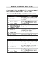
Chapter 9   Optional Accessories

4 3

No.

Item

Function

4

Mini SNMP Card 

Monitors and controls the status of the 
UPS via a network system.

5

Mini Relay I/O Card 

Increases the quantity of dry contacts.

6

Mini USB Card

Lets the UPS have USB communication 
function.

7

Mini ModBus Card

Lets the UPS have ModBus 
communication function.

8

Mini TVSS Card 

Lets the UPS have surge protection 
function.

z

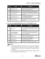
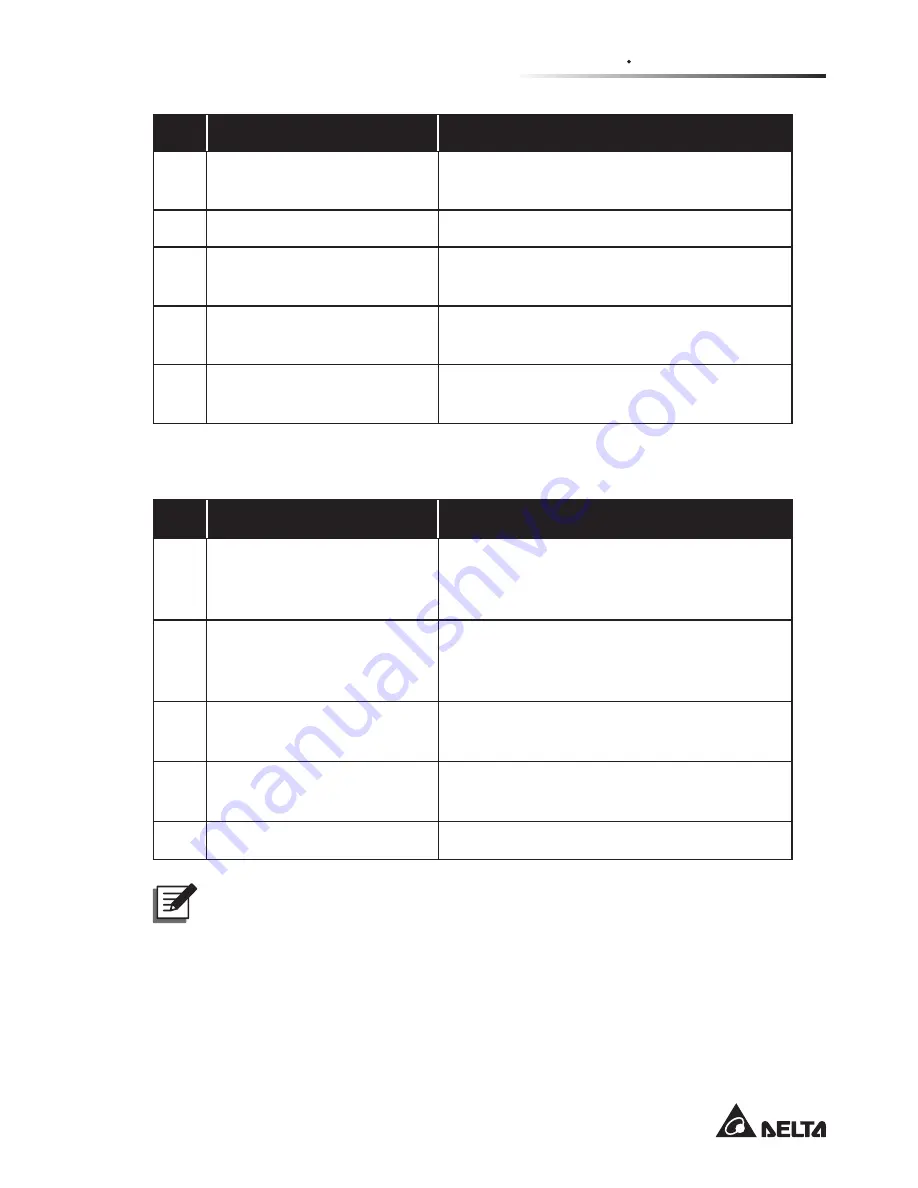
For models UPS602N2004N0BA (6kVA) & UPS103N2004N0BA (10kVA)

No.

Item

Function

1

Dust Filter

Prevents dust from entering into the UPS 
to ensure UPS reliability and to prolong 
product life.

2

Manual Bypass Box 
(Single/ Parallel)

Lets the UPS continue supplying power 
to its connected loads when the UPS is 
under maintenance.

3

SNMP Card

Monitors and controls the status of the 
UPS via a network system.

4

ModBus Card

Lets the UPS have ModBus 
communication function.

5

Relay I/O Card

Increases the quantity of dry contacts.

NOTE : 

1.  For detailed installation and operation of any accessory mentioned 

above, please refer to the Quick Guide, User Guide, or Installation 
& Operation Guide included in the package of the relevant optional 
accessory.

2.  If you want to buy any accessory mentioned above, please contact 

your local dealer or customer service.

Содержание N-10K

Страница 1: ...www deltapowersolutions com Delta UPS Amplon Family User Manual The power behind competitiveness N Series Single Phase 6 10 kVA ON OFF SETUP...

Страница 2: ...s product Any disposition duplication dissemination reproduction modification translation extraction or usage of this Manual in whole or in part is prohibited without the prior written permission of D...

Страница 3: ...3 Operation Panel 9 3 1 LED Indicators 9 3 2 Multi function Buttons 10 3 3 LCD Display 13 3 4 7 Segment Display 15 3 5 16 Segment Display 17 3 6 Error Code Information 18 3 7 LCD Display Flow Chart 1...

Страница 4: ...f Procedures 39 7 1 Turn on Procedures 39 7 2 Turn off Procedures 40 Chapter 8 Alarm 41 Chapter 9 Optional Accessories 42 Chapter 10 Troubleshooting 44 Chapter 11 Maintenance 47 11 1 UPS 47 11 2 Batte...

Страница 5: ...he UPS must be well grounded due to a possible risk of current leakage z The installation of upstream and downstream protective devices is highly recom mended when the UPS is connected to the mains an...

Страница 6: ...PS Before cleaning please make sure that the UPS has been completely shut down and the con nection between the UPS and the input power and the connection between the UPS and the external battery pack...

Страница 7: ...pacity may occur during shipping and storage Before 1st use of the UPS please fully charge the batteries until the Battery Level Bar Graph shown on the UPS s LCD is fully on z If the UPS needs to be s...

Страница 8: ...ut down disconnect the UPS from the utility power remove all loads from the UPS and store the UPS in a dry and well ventilated area at a temperature between 15 C and 50 C Idle batteries must be rechar...

Страница 9: ...tput power factor up to unity DQG LWV HI FLHQF LQ RQ OLQH PRGH FDQ UHDFK DW PD LPXP 7KH 836 QRW RQO provides safe reliable and uninterrupted power to your sensitive electronic equip PHQW DW DOO WLPHV...

Страница 10: ...power behind competitiveness N Series Single Phase 6 10 kVA ON OFF SETUP ON OFF SETUP 3 4 5 6 7 8 9 10 x 3 x 4 x 2 x 6 No Item Q ty 1 UPS 1 PC 2 Parallel Cable 1 PC 3 User Manual 1 PC 4 Battery Cable...

Страница 11: ...eries Single Phase 6 10 kVA ON OFF SETUP ON OFF SETUP 3 4 5 6 7 8 9 10 11 x 2 x 4 x 3 x 2 x 6 No Item Q ty 1 UPS 1 PC 2 Parallel Cable 1 PC 3 User Manual 1 PC 4 CU Terminal_ Type A 2 PCS 5 CU Terminal...

Страница 12: ...PC 3 User Manual 1 PC 4 CU Terminal_ Type A 2 PCS 5 CU Terminal_ Type B 4 PCS 6 CU Terminal_ Type C 3 PCS 7 Battery Terminal Box 1 PC 8 Battery Terminal Box Cover 1 PC 9 Screw for Battery Terminal Box...

Страница 13: ...3 1 LED Indicators 3 3 LCD Display including 3 4 7 Segment Display 3 5 16 Segment Display 3 2 Multi function Buttons 3 1 LED Indicators No LED Description 1 Indicates the output status 1 On green Ther...

Страница 14: ...onds release it after you hear one beep and the UPS will run in on line mode z Cold start When there is no AC input press and hold the button for 3 seconds release it after you hear one beep and the U...

Страница 15: ...ons com en in mcis software FHQWHU SKS RU FRQ JXUH WKH PLQL 6103 FDUG RSWLRQDO or mini ModBus card optional 3 Scrolling Up Increasing Number z Press the button for 0 1 second to go to the previous dis...

Страница 16: ...rned off For more information please refer to UURU RGH QIRUPDWLRQ and KDSWHU 7URXEOHVKRRWLQJ 4 ON SETUP z Entering into the Setup Mode Simultaneously press the and ON these two buttons for 3 seconds t...

Страница 17: ...erate in on line mode 3 OFF The AC input is out of the acceptable bypass range and is not able to let the unit operate in on line mode 2 Output Icon Indicates the output status 1 ON There is output 2...

Страница 18: ...uminates when the UPS is operating in by pass mode 10 ECO Mode Graph Illuminates when the UPS is operating in ECO mode 11 ECO ECO Mode Illuminates when the UPS is operating in ECO mode It is bypass to...

Страница 19: ...DO FDSDFLW RI WKH FRQQHFWHG loads 1 2 Flashing Overload 15 Battery Level Bar Graph 1 ON 7KH UHPDLQLQJ EDWWHU FDSDFLW 1 2 Flashing Low battery NOTE 1 means that WKH st segment will illuminate WKH UVW W...

Страница 20: ...ation such as input voltage output voltage output frequency load capacity etc 2 SET Setup mode Please refer to 6HWXS 0RGH Status 3 IN Input 4 OUT Output 5 BATT Battery status 6 LOAD Load status 7 TEST...

Страница 21: ...g Category 1 16 segment display Number Error code For error code information please refer to UURU RGH QIRUPDWLRQ The combination of the three cat egories left hand side presents relevant infor mation...

Страница 22: ...and four numbers such as E2303 E0301 E2002 E2702 etc The display of the error code shown on the 16 segment display is presented by two alternate screens and each screen appears for 0 5 second Please...

Страница 23: ...y mode except battery mode here displays the input voltage 3 7 LCD Display Flow Chart 7KH IROORZLQJ RZ FKDUW KHOSV RX WR XQGHUVWDQG KRZ WR JR WKURXJK HDFK GLVSOD screen Here we take Bypass Mode as an...

Страница 24: ...UT BATT RUN TIME C LOAD TEST Hz KW KVA AH MIN MIN ECO V V IN SET IN OUT BATT RUN TIME C LOAD TEST Hz KW KVA AH MIN MIN ECO V V IN SET IN OUT BATT RUN TIME C LOAD TEST Hz KW KVA AH MIN MIN ECO V V IN S...

Страница 25: ...UT N N L L AC INPUT 1 2 3 4 5 6 7 8 9 10 11 12 13 No Item Functions 1 For external battery pack s grounding 2 External Battery Connector Connects to the external battery pack 3 Smart Slot Accepts an S...

Страница 26: ...r supplied normally open switch to the REPO port When the user supplied switch is closed the UPS will immediately shut down the inverter and output the UPS won t transfer into bypass mode 11 USB Port...

Страница 27: ...12 No Item Functions 1 External Battery Connector Connects to the external battery pack 2 Mini Slot Accepts an mini SNMP mini Relay I O mini USB and mini ModBus card optional 3 Parallel Ports For UPS...

Страница 28: ...port When the user supplied switch is closed the UPS will immediately shut down the inverter and output the UPS won t transfer into bypass mode 10 USB Port Connects to your computer You can monitor th...

Страница 29: ...7 8 9 10 11 12 No Item Functions 1 External Battery Connector Connects to the external battery pack 2 Smart Slot Accepts an SNMP Relay I O USB and ModBus card optional 3 Parallel Ports For UPS paralle...

Страница 30: ...port When the user supplied switch is closed the UPS will immediately shut down the inverter and output the UPS won t transfer into bypass mode 10 USB Port Connects to your computer You can monitor th...

Страница 31: ...LIXI CDB6i1252D63 O P DELIXI CDB6i1252D63 10kVA D Curve 80A Breaker I P DELIXI CDB6i1252D80 O P DELIXI CDB6i1252D80 z Check that the size diameter phase and polarity of each cable that needs to connec...

Страница 32: ...t output wiring methods are the same Below we only use model UPS103N2004N0B0 10 kVA as an example for illustration 1 Remove the two screws from the wiring panel shown below LJXUH 5HPRYDO RI LULQJ 3DQH...

Страница 33: ...the input grounding cable and output grounding cable and then connect the two CU terminals type A to the input grounding terminal and output grounding terminal NOTE To avoid output from over current p...

Страница 34: ...For models UPS602N2004N035 6 kVA UPS103N2004N035 10 kVA 1 Remove the two screws from the external battery connector s panel shown below LJXUH 5HPRYDO RI WHUQDO DWWHU RQQHFWRU V 3DQHO After Removal of...

Страница 35: ...ctor and use the two screws that were removed from the external battery connector s SDQHO WR UPO WKH EDWWHU FDEOH KROGHU RQ WKH RXWHU FDVLQJ 1 Use the provided CU terminal type A 2 to connect with the...

Страница 36: ...s panel shown below LJXUH 5HPRYDO RI WHUQDO DWWHU RQQHFWRU V 3DQHO After Removal of External Battery Connector s Panel Before Removal of External Battery Connector s Panel ON OFF RS 232 REPO REPO PARA...

Страница 37: ...O WR UPO WKH SURYLGHG EDWWHU WHUPLQDO ER 2 on the outer casing Use the two provided battery terminal box cover s screws 3 WR UPO WKH SURYLGHG EDWWHU WHUPLQDO ER FRYHU 4 on the provided battery termina...

Страница 38: ...led After the UPS is connected to the AC utility it will supply power to the UPS and the batteries will be charged 6 2 On line Mode In online mode the connected loads are supplied by the inverter whic...

Страница 39: ...04N0B0 10 kVA You can install the UPSentry 2012 software please download from http www deltapowersolutions com en in mcis software center php or the mini SNMP card optional or the mini ModBus card opt...

Страница 40: ...or the next display 3 Press the button for 0 1 second to enter into the item that you want to set up 4 Press the ON button for 0 1 second or press the OFF button for 0 1 second to increase or decreas...

Страница 41: ...nal Display Inverter Voltage Setup Inverter Frequency Setup Parallel ID Setup Battery String Setup Battery Capacity Setup Charge Current Setup Buzzer Setup Overload Alarm Setup ECO Mode Setup Frequenc...

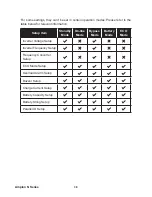
Страница 42: ...below for relevant information Setup Item Standby Mode On line Mode Bypass Mode Battery Mode ECO Mode Inverter Voltage Setup Inverter Frequency Setup Frequency Converter Setup ECO Mode Setup Overload...

Страница 43: ...nce parallel reliability please adopt the Daisy Chain method to execute parallel FRQ JXUDWLRQ 3OHDVH QRWH WKDW SDUDOOHO 836V FDQQRW VKDUH FRPPRQ batteries 2 Only when the parallel icon illuminates can...

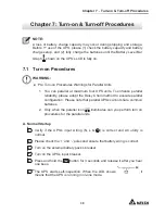
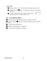
Страница 44: ...arts self inspection When the LCD shows it means that the UPS is running in battery mode 7 2 Turn off Procedures 1 Make sure that the connected loads have been completely turned off 2 Press and hold t...

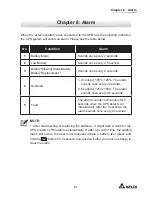
Страница 45: ...ORDGB a 7KH DODUP sounds once every 2 seconds 2YHUORDGB a 7KH DODUP sounds once every 0 5 seconds 5 Fault The alarm sounds continuously for 5 seconds when the UPS detects an internal fault After the 5...

Страница 46: ...Cable Extension Kit includes two ring type thimbles and two joints Extends the provided battery cable 1 5m 4 SNMP Card Monitors and controls the status of the UPS via a network system 5 ModBus Card Le...

Страница 47: ...he UPS to ensure UPS reliability and to prolong product life 2 Manual Bypass Box Single Parallel Lets the UPS continue supplying power to its connected loads when the UPS is under maintenance 3 SNMP C...

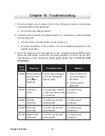
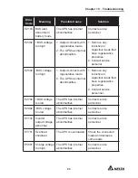
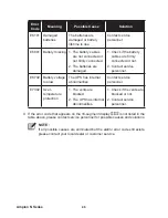
Страница 48: ...low to solve the according problems To know how the error code appears on the 16 segment display please refer to UURU RGH QIRUPDWLRQ Error Code Meaning Possible Cause Solution E0002 Abnormal input whe...

Страница 49: ...s with regenerative loads 2 The UPS has internal abnormalities 1 Remove any inductive or capacitive loads that have regenerative properties 2 Contact service personnel E2702 BUS voltage too low The UP...

Страница 50: ...onnel E6702 Battery voltage too low The UPS has internal abnormalities Contact service personnel E7302 Over temperature protection 1 The vents are blocked 2 The UPS has internal abnormalities 1 Check...

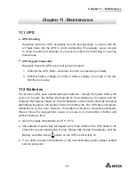
Страница 51: ...hough the typical battery life cycle is 3 5 years the battery life depends on the temperature the usage and the charging discharging frequency High temperature environments and high charging dischargi...

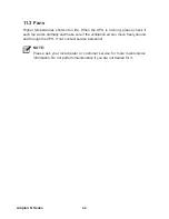
Страница 52: ...ase check if each fan works normally and make sure if the ventilation air can move freely around and through the UPS If not contact service personnel NOTE Please ask your local dealer or customer serv...

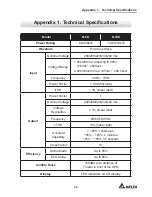
Страница 53: ...0 230 240 Vac 195Vac 280 Vac 2 Frequency 40Hz 70Hz Power Factor 0 99 full load iTHD OLQHDU ORDG Output Power Factor 1 Nominal Voltage 200 208 220 230 240 Vac Voltage Regulation OLQHDU ORDG Frequency 5...

Страница 54: ...0 Model REPOx1 RS 232 Portx1 USB Portx1 Parallel Portx2 Mini Slotx1 Physical Dimensions W x D x H 190x390x325 mm Weight 10 1 kg 12 7 kg Environment Operating Altitude 1000 meters without derating Oper...

Страница 55: ...sistible force i e war fire natural disaster etc and this warranty also expressly excludes all incidental and consequential damages Maintenance service for a fee is provided for any damage out of the...

Страница 56: ...5013243801...

Отзывы: