background image

Triplex Real Time Stand Alone DVR

53

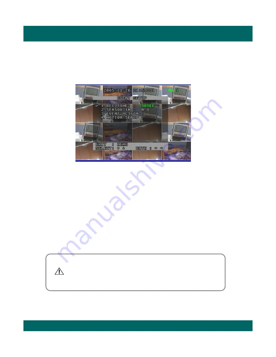
6.4. Event Setup 

This screen enables simple set up of DVR motion detection, alarm and external sensor configurations.

6.4.1 REC Time                     3 sec ~ 30 min

Once event recording is triggered, the video will be recorded compulsorily during the time  

selected by the user or administrator.

6.4.2 Sensor In                      N.O/N.C

The Sensor-in terminals of the DVR are used to connect external motion sensors or door/window

contacts. 
There are two types of general sensors in the market. The one is "normal mode-open“, N.O, which 
means two sensor lines are not connected (open) in the normal mode but the lines are to be 
connected (close) in the activation mode. The other is "normal mode-close“, N.C,  which means two 
sensor lines are connected (close) in the normal mode but the lines are to be disconnected (open)
in the activation mode.

• To return to menu, press Menu button.

You have to make sure of sensor type between N.O and N.C 

before installation.   Otherwise, it may not work properly.

- N.O : Normal Open type sensor
- N.C : Normal Close type sensor

Содержание HSD

Страница 1: ...Triplex Real Time Stand Alone DVR 1 User s Manual Triplex Real Time Stand Alone DVR 4 8 16 Channel DVR ...

Страница 2: ...tion against harmful interference when the equipment is operated in a commercial environment Please beware of the following precautions before installing the DVR Avoid any place with moisture dust or soot Avoid any place with direct sunlight or heating appliances Keep the product away from electric shock or magnetic substances Avoid high or low temperature Recommended operation temperature is betw...

Страница 3: ... 2 2 CAMERA 4 2 3 MONITOR 4 2 4 VGA 4 2 5 AUDIO 4 2 6 USB CHAPTER 5 OPERATION 5 1 FACTORY DEFAULT 5 2 FRONT PANEL CONTROL FUNCTION 5 2 1 MULTI DISPLAY 5 2 2 PIP DISPLAY 5 2 3 AUTO SEQUENCE DISPLAY 5 2 4 TRIPLEX DISPLAY 5 2 5 DVR INFORMATION 5 2 6 RECORD 5 2 7 SEARCH PLAYBACK 5 3 REMOTE CONTROLLER 5 3 1 REMOTE CONTROL FUNCTION 5 3 2 MUTE Contents 6 7 8 9 10 13 14 15 15 16 17 18 18 19 19 20 9 21 22 ...

Страница 4: ... 6 3 DISPLAY SETUP 6 3 1 BLANK CHANNEL SETUP 6 3 2 PIP CHANNEL SETUP 6 3 3 ADJUST CHANNEL SETUP 6 3 4 VIDEO SIGNAL TYPE 6 3 5 SEQUENCE 6 3 6 BOUNDARY COLOR 6 3 7 BLANK COLOR 6 4 EVENT SETUP 6 4 1 RECORD TIME 6 4 2 SENSOR IN 6 4 3 EVENT ACTION 6 4 4 MOTION SETUP 6 5 RECORD SETUP 6 5 1 RECORD TYPE 6 5 2 RECORD SPEED 6 5 3 RECORD QUALITY 6 5 4 PB SPEED 6 5 5 CHANNEL ENABLE 6 5 6 AUDIO SETUP Contents ...

Страница 5: ...tional 7 4 ETHERNET USB CHAPTER 8 SPECIFICATIONS CHAPTER 9 HDD CD RW INSTALLATION 9 1 HDD INSTALLATION 9 2 CD RW INSTALLATION CHAPTER 10 CLIENT NETWORK VIEWER MANUAL 10 1 SYSTEM REQUIREMENT 10 2 NETWORK ENVIRONMENT 10 3 NETWORK VIEWER INSTALLATION 10 4 NAMES FUNCTIONS 10 5 OPERATION 10 5 1 LIVE VIEW MODE 10 5 2 PLAY BACK MODE 10 5 3 DRIVE SCAN MODE 10 5 4 FILE PLAY MODE 10 5 5 CD PLAY MODE CHAPTER...

Страница 6: ...Quad 6 8 9 13 16 split Search by date time list event list and data time Playback speed mode to be adjustable Recording Recording quality level to be adjustable Camera frame rate can be set by user The recording speed of max 120 images per second NTSC Manual schedule and event motion alarm recording Recording image size EACH CIF to be adjustable 1 channel audio recording Network Live and playback ...

Страница 7: ...ote backup on network PC with the exclusive client viewer CD RW backup USB 2 0 backup Video file Still image backup General PAL NTSC in a display setup menu to be adjustable Built in hardware Watchdog S Video output Alarm In Out RS 485 RS 232 Connections Loop through connections Multiple Languages VGA output for PC monitor Optional ...

Страница 8: ... controller 3 User s Manual 1 DVR unit 2 Network Viewer Program CD 5 LAN Cable 7 Power Cord 6 DC Adaptor 9 HDD Screws 8 Battery CONTENTS 1 DVR unit 2 Network Viewer Program CD 3 User s Manual 4 Remote controller 5 LAN Cable 6 DC Adaptor 7 Power Cord 8 Battery 9 HDD Screws ...

Страница 9: ...k LED light turns on 4 PLAY ON means the DVR is in search mode of playback 5 REC ON means the DVR is on recording 6 Remote Controller Sensor 7 MULTI It converts to live display mode directly To surf various live display modes like 16CH 13CH 9CH 8CH and 6CH display by pressing the button repeatedly 8 PIP To convert to PIP mode Picture in Picture To surf various PIP modes like 1PIP 2PIPs and 3PIPs b...

Страница 10: ...ss the button in playback mode you will see 8 channel live displays and 8 channel playbacks that you have selected 11 INFO INFORMATION BACKUP To show system information of DVR press it in live display mode To backup videos press it and select CD RW or USB in playback mode 12 CD Burner To burn CD for data back up 13 REWIND Select speed level among 4 levels 14 PLAY PAUSE II To play and pause the rec...

Страница 11: ...Triplex Real Time Stand Alone DVR 11 3 2 REAR PANEL 1 2 4 12 13 16CH DVR 7 6 3 5 9 10 8 11 8CH DVR 4CH DVR ...

Страница 12: ...external devices 6 Audio In Out Port 7 USB 2 0 Port 8 RS 232 Port 9 Pin D Sub Connector 9 Alarm In Out and RS 485 Port 25 Pin D Sub Connector It is to communicate with external sensors alarm and PTZ camera to control 10 S Video Output 11 LAN Terminal It is to connect to LAN or Internet 12 BNC connectors for monitor output These are mainly for monitors And also you can use these for VCR recorder ba...

Страница 13: ...Triplex Real Time Stand Alone DVR 13 CHAPTER 4 INSTALLATION 4 1 TOTAL CONNECTION DIAGRAM ...

Страница 14: ...VR 14 4 2 INDIVIDUAL CONNECTION 4 2 1 POWER 4 2 2 CAMERA 16 Cameras Connect the DC adaptor provided in the package And then turn on the power switch Connect a female BNC connector of each camera to a male BNC connector CAMERA IN port ...

Страница 15: ... 15 4 2 3 MONITOR 4 2 4 VGA Optional Connect the female BNC for monitor output Connect the male DIN socket for S VIDEO monitor output S VIDEO Main Monitor Connect the D sub connector of computer VGA monitor to VGA out of DVR PC monitor ...

Страница 16: ...dio Output AUDIO OUT Connect the RCA Line output to a monitor with a built in speaker Note Note This DVR can be connected only with a line audio and not support a microphone for audio input and output To record audio AUDIO function should be enable in the AUDIO setup of main menu As the audio is linked to a camera it is required that linked camera should be viewed in the screen during playback in ...

Страница 17: ...Stand Alone DVR 17 4 2 6 USB USB 2 0 port The USB port is provided to connect USB memory stick for video backup still image copying Note Note For further details please go to USB backup page 36 How to operate USB backup ...

Страница 18: ...ud Rate ON Record Beep ON HDD Fail Blank Channel Setup PIP Channel Setup Adjust Channel Setup Sequence Boundary Blank CH1 CH16 OFF CH 1 Main CH 2 Sub 1 CH 3 Sub 2 Sub 3 CH 4 Channel CH 1 50 CON 50 HUE 50 BRI COL 50 1 sec White Blue Rec Time Sensor In Event Action Motion Setup 30 sec N O ON Alarm Out BEEP OSD Sensor OSD Video Loss Motion OFF CH 1 Channel 9 Sensitivity Area Full Quality PB Speed Aud...

Страница 19: ...PLAY functions in any mode It converts to 16 channel live display on the screen as below by pressing MULTI button To convert to live display press MULTI button in any mode You can surf 13 CH 9 CH 8 CH 6 CH display by pressing MULTI button repeatedly 13 CH display Mode 9 CH display Mode 6 CH display Mode 8 CH display Mode ...

Страница 20: ... monitoring multiple channels while focusing more attention on a particular channel It has a main video channel view and up to 3 small video channel views on the screen You can surf 1 PIP 2 PIPs 3 PIPs mode with 4 positions by pressing PIP button repeatedly To release this mode press MULTI button on the front panel 1PIP 2 PIPs 3 PIPs 5 2 2 PIP DISPLAY ...

Страница 21: ...n the order of CH 1 CH 2 CH3 CH 15 CH 16 16 channel mode and keep the order until you press MULTI button The DVR skips channels with no video You can find that the DVR indicates AUTO in the upper left of the screen in this mode To release this mode press AUTO button again CH 1 CH 3 CH 2 CH 15 CH 16 16 CH CIF Mode It indicates current status is in Auto Sequence mode ...

Страница 22: ...play mode and playback mode with each channel 1 8 as below Press TRI button three times repeatedly it returns to 16ch playback mode To surf the other 8 channel live display and playback with each channel 9 16 press MULTI button or Up Down button in the remote controller If you press channel button in this mode you can see the full channel video of playback mode in the screen To exit to live displa...

Страница 23: ...layback videos at that time Press TRI button three times repeatedly it returns to 16ch playback mode with no videos To surf the other 8 channel live display and playback with each channel 9 16 press MULTI button or Up Down button in the remote controller To return to live display mode press Multi button or TRI button again 16CH Live Display Triplex Mode 1 Triplex Mode 2 It shows no videos in black...

Страница 24: ...r HDD Rec It means the capacity of used HDD Over It means how many times the HDD is overwritten 2 SLAVE Model It shows the model no of Slave HDD Size It shows the size of Slave HDD Rec It means the capacity of used HDD Over It means how many times the HDD is overwritten 3 CD RW It shows the model no of CD RW installed in the DVR 4 USB DRIVE It shows USB detection and USB capacity for data backup i...

Страница 25: ...e display mode which is one of our main features that is simultaneous multi function operation in one screen MA PLAY It plays videos that have been stored in Master HDD SL PLAY It plays videos that have been stored in Slave HDD 3 It means that audio function is set to channel 1 default Users can select one channel audio function among 16 channels as they desire 2 3 Schedule Record Mode When Schedu...

Страница 26: ...ecording in the list press ENTER button where the recording is highlighted The DVR will playback the recording You can stop the video at any time by pressing STOP button 5 2 7 1 DATE TIME LIST SEARCH 1 Press SER button on the front panel 2 Select Date Time List Search by using Up Down button and press ENTER button 3 Select one between MASTER and SLAVE by pressing SER button 4 Select your desired o...

Страница 27: ...f the list is the right one that you select and then press ENTER button again 6 It plays the list To be out of this menu press MENU button repeatedly 5 2 7 3 DATE TIME SEARCH 1 Press SER button on the front panel 2 Select Date Time Search by using Up Down button and press ENTER button 3 Select one between MASTER and SLAVE by using ENTER button 4 Type in specific date time upon your desired list by...

Страница 28: ... 13 Down 14 ENTER 15 All Search menu 16 Time Search by date time 17 List Search by date time list 18 Stop 19 REW x2 x4 x8 x16 rewind 20 FF x2 x4 x8 x16 x32 x64 fast forward 21 Play 22 II Pause 23 P B Playback 24 TRI Triplex 25 Panorama 26 P T Pan Tilt 27 Z F Zoom Focus 28 CD RW Backup 29 USB Backup 5 3 1 REMOTE CONTROLLER FUNCTIONS 3 4 5 6 7 8 9 10 11 12 13 15 23 24 16 17 25 26 14 18 19 20 21 22 2...

Страница 29: ...ct MUTE function in the remote controller 1 Press MUTE button in the remote controller when monitoring or playing the video with audio 2 The activated icon in green in the upper right of screen is changed to one in gray with this function 3 The DVR makes it silent To release this function press MUTE button again ...

Страница 30: ...And then press Zoom button again 4 You can see the video that is magnified two times digitally 5 To exit this mode push Zoom button again in the remote controller You can magnify a certain part of the full size screen two times digitally when you use this function as described below This function can be applied to all display and search modes You can operate this function with only remote controll...

Страница 31: ... playback mode 1 Select and play your desired video in the recording list first 2 Press PANORAMA button in the remote controller 3 Select your desired channel by pressing PANORAMA button repeatedly 4 To exit this function press MULTI button Press PANORAMA button again in PANORAMA mode and you will return to playback mode To be out of playback mode press STOP button Note Note ...

Страница 32: ... press P T button again and then P T disappears on the screen 5 3 5 1 Pan Tilt Function 1 16 channel display mode 2 One channel Mode It indicates Pan Tilt function 1 First select your desired channel installed in Pan Tilt camera by pressing channel selection button 2 And then you will see a full size screen 3 Press P T button in the remote controller 4 Control the camera with the direction buttons...

Страница 33: ...ns Up Down Right Left 5 To release this function press Z F button again in the remote controller It indicates Zoom Focus function 1 First press Z F button in the remote controller 2 Select your desired channel by pressing channel selection button directly 3 Control the camera with the direction buttons Up Down Right Left 4 To release this function press Z F button again and then Z F disappears on ...

Страница 34: ...me and recording time on the screen 2 Press Enter button It pauses playback mode and shows CD RW backup checking on the screen which may take some time to complete Checking 3 It indicates that it is ready for CD RW backup mode showing Ready on the screen to users Press Enter button and then it starts CD RW backup showing Setting on the screen 5 3 6 BACKUP 5 3 6 1 CD RW BACKUP ...

Страница 35: ...ist continuously right from the pause point To return to live display mode press Stop button 6 The burned CD comes out automatically from CD RW showing Close on the screen In case that the list size is bigger than blank CD capacity you can continue to backup the remained size with another blank CD Î Insert new one into DVR and press Enter button It continues to backup the remained size of the list...

Страница 36: ...the Information menu if DVR detects it or not 2 Select the desired recording list and play it It plays the list in CIF mode as left 3 To operate USB backup function press Backup button in the front panel or USB button in remote controller at your convenience Select USB and then press Enter button USB stick memory format in your PC You have to format it by only FAT 32 as file system Note Note ...

Страница 37: ...ng Backup on the screen It updates stop time and recorded USB capacity as it stores the data in the USB memory stick You can stop the USB backup by pressing backup button or USB backup button in the remote controller at any time as you want 7 To stop it press Backup button or USB in remote controller again It stops USB backup showing Close on the screen And it pause playback mode It may take some ...

Страница 38: ...SB memory stick by using only network viewer program to be provided in the package For further details please refer to page 75 Note Note If you remove USB stick in the process DVR may be shut down or in crash CAUTION CAUTION 8 To get out of this mode press backup button And press Play button and then it plays the list continuously right from the pause point To return to live display mode press Sto...

Страница 39: ...he desired recording list It plays the list in CIF mode And then select one channel that you want 3 Press Backup button in the front panel or USB button in remote controller at your convenience USB STILL is displayed and disappeared on the bottom of screen USB memory stick starts storing it showing that the LED of USB stick flickers USB stick memory format in your PC Users have to format it by onl...

Страница 40: ...le in USB memory stick by using only network viewer program to be provided in the package For further details please refer to page 75 Note Note 1 If you remove USB memory stick in the process of backup DVR may be shut down or in crash 2 You cannot store still images in USB memory stick in the pause mode of playback CAUTION CAUTION 5 You can find the file in USB memory stick S 051121 091025 0001 dv...

Страница 41: ...Stand Alone DVR 41 CHAPTER 6 SETUP MENU 6 1 Language When you first call the main menu via the MENU button you ll see that the current language is highlighted see screen shot above To exit to main menu press MENU button ...

Страница 42: ...mode MA REC shows videos are recorded in master hard disk SL REC shows videos are recorded in slave hard disk 3 Format To format the HDD press ENTER button and then select YES To return to main menu press MENU button 6 2 1 HDD Setup This menu enables HDD setup Note Note You have to make sure of it before HDD format Once HDD formatted you are not able to retrieve any video that has been recorded pr...

Страница 43: ...sired 4 digit password among 0 9 by pressing ENTER direction button To return to the sub menu press MENU button after completing password input To return to main menu press MENU button 6 2 2 Password Setup This menu allows to choose system password Remember that the password is set to 1111 as factory default Note Note ...

Страница 44: ...isplay of camera names in playback mode When turned OFF it disables display of camera names in playback mode 3 CH 1 CH 16 CH 1 2 16 When the pointer is located next to CAMERA1 2 3 4 14 15 16 1 Press ENTER button 2 See the active cursor on the first letter of which means a blank 3 Surf along letters by pressing Up Down button 4 When you find your desired letter press Right Left button to move the a...

Страница 45: ...FF When turned ON it enables display of date time in playback mode When turned OFF it disables display of date time in playback mode 3 Type YY MM DD DD MM YY MM DD YY 4 Date 2005 05 11 5 Time 20 51 49 When the pointer is located next to Date or Time 1 Press ENTER button 2 Set Date or Time To Select it by pressing Up Down button To Move to the next by pressing Left Right button 3 When you finish se...

Страница 46: ...select PTZ camera speed among 5 levels Lower level makes the camera speed slower 3 Baud Rate 2400 BPS 12400 BPS Users can select Baud rate to be in accordance with one of installed cameras For example if you install a camera with the protocol of PELCO P 4800 you have to select PTZ type as PELCO P and baud rate as 4800 BPS Bits Per Second Compatible Pan Tilt camera list All cameras using LG Hitron ...

Страница 47: ... OFF To enable to beep when the DVR detects a bad sector of HDD in recording mode or playback mode It skips the bad sector detected and records videos or plays recorded videos in the next sector of bad sector automatically HDD is logically divided to a large amount of sectors It may have some bad sectors out of a large amount of it When this function is on you are recommended to exchange with new ...

Страница 48: ...e to make channels hidden behind the screen during live display mode as below CH 1 CH 16 ON OFF To return to main menu press MENU button 6 3 Display Setup Even though some channels are hidden behind the screen during live display mode DVR is recording them in HDD Note Note ...

Страница 49: ...l screen or sub channel among 16 channels To return to main menu press MENU button 6 3 2 PIP Channel Setup You can select PIP Picture In Picture options PIP mode offers a convenient way of monitoring multiple channels while focusing more attention on a particular channel It has a main video channel view and up to 3 small video channel views on the screen ...

Страница 50: ...djust video display 2 CON Contrast 50 To control light and shade of video display 3 HUE 50 To control color tone of video display 4 BRI Brightness 50 To control brightness of video display 5 COL Color 50 To control saturation of color of video display To return to main menu press MENU button Default factory mode is set to 50 Remember that the values range is from 01 to 99 Note Note ...

Страница 51: ...tem automatically after your selection Once it reboots all data that you had selected previously is set to factory default 6 3 5 Sequence 1 sec 1 min To select interval time of Auto Switch With the Auto Sequence feature a range of interval time among some different views can be selected AUTO mark in the left top of screen indicates Auto Sequence mode In this mode it may skip the channels with no v...

Страница 52: ... DVR 52 6 3 6 Boundary White Black OFF To select the boundary color that is divided into each channel 6 3 7 Blank Blue Black To select the background color of no video channels between two colors To return to menu press MENU button ...

Страница 53: ...r door window contacts There are two types of general sensors in the market The one is normal mode open N O which means two sensor lines are not connected open in the normal mode but the lines are to be connected close in the activation mode The other is normal mode close N C which means two sensor lines are connected close in the normal mode but the lines are to be disconnected open in the activa...

Страница 54: ...om the cameras do not reach the DVR a beep will sound to get your attention BEEP OSD Beeps and shows L mark together in the channel with video loss OSD On Screen Display only OFF Disables to activate the alarm action 4 Motion BEEP OSD OSD OFF When DVR detects motion on a certain part of the screen DVR will beep or OSD to get your attention BEEP OSD Beeps and shows MO mark together in the channel w...

Страница 55: ...select motion areas FULL Select full area as motion area SET To select the area as you desire move to POSITON menu 4 Position Press Enter button and surf areas in the desired channel by pressing direction button and then press ENTER button to select press it again to release Once you select the areas you don t need to select them again when you get back from other modes like OFF or FULL It gives y...

Страница 56: ...range of fps available varies NTSC and PAL have the following fps available NTSC 1 60 F S Each Mode 120 F S CIF Mode PAL 1 50 F S Each Mode 100 F S CIF Mode 6 5 3 Quality Level 1 6 It is to set video quality from level 1 to level 6 The higher the video quality the more HDD space needed High quality has lower network transmission due to image size 6 5 4 PB Speed AUTO 1 60 F S EACH mode 120F S CIF m...

Страница 57: ...FF To enable icon of audio function in the upper right of screen as below 6 5 7 Schedule Setup 1 Schedule ON OFF To disable OFF or enable ON Schedule recording feature 2 Day Daily SUN SAT Select the desired day for schedule recording Daily Sun Mon Tue Wed Thu Fri Sat 3 Time When you finish to set Day press ENTER button to go into the Timeline Surf left or right in the timeline by pressing Left or ...

Страница 58: ...net The videos are displayed in network viewer from channel 1 in sequence Ethernet doesn t update channel 2 until channel 1 is displayed 6 6 6 Network ID 8 letters 6 6 7 Password 8 letters You must register your Network ID before using network viewer program first Press Enter button and type in network ID Password by pressing direction button To access to network viewer program you need to type in...

Страница 59: ...lex Real Time Stand Alone DVR 59 CHAPTER 7 EXTERNAL TERMINAL INFORMATION 7 1 RS 232 16CH DVR 1 2 3 4 5 6 7 8 9 N C TX 232C RX 232C N C GND 6 9 N C N C Connection Not Required Description 2 3 4 5 1 No RS 232 ...

Страница 60: ...2 13 11 14 15 16 17 18 20 21 22 23 25 24 19 Alarm In GND RX 232C TX 232C GND 21 Alarm Out COM 22 Alarm Out NO 8CH DVR 9 14 15 16 17 20 1 8 No Alarm In GND RX 232C TX 232C GND 24 485A 25 485B 4CH DVR 5 14 15 16 17 20 1 4 No 23 Alarm Out NC 24 485A 25 485B 21 Alarm Out COM 22 Alarm Out NO 23 Alarm Out NC ...

Страница 61: ... DVR 61 7 2 ALARM IN OUT RS 485 16CH DVR Alarm In Out RS 485 1 2 3 4 5 6 7 8 9 10 12 13 11 14 15 16 17 18 20 21 22 23 25 24 19 Alarm In GND Alarm Out COM Alarm Out NO Alarm Out NC 24 485A 25 485B Description 17 20 21 22 23 1 16 No ...

Страница 62: ...2 13 11 14 15 16 17 18 20 21 22 23 25 24 19 Alarm In GND RX 232C TX 232C GND 21 Alarm Out COM 22 Alarm Out NO 8CH DVR 9 14 15 16 17 20 1 8 No Alarm In GND RX 232C TX 232C GND 24 485A 25 485B 4CH DVR 5 14 15 16 17 20 1 4 No 23 Alarm Out NC 24 485A 25 485B 21 Alarm Out COM 22 Alarm Out NO 23 Alarm Out NC ...

Страница 63: ...VR 4CH DVR 8CH DVR 1 2 3 4 5 6 7 8 9 10 11 12 13 14 15 14 15 Description 2 3 4 12 13 1 No VSYNC Vertical Sync Reserved GREEN Green Video 75ohm 0 7Vp p BLUE Blue Video 75ohm 0 7Vp p Reserved HSYNC or CSYNC Horizontal or Composite Sync RED Red Video 75ohm 0 7Vp p ...

Страница 64: ...CH DVR 1 USB 2 ETHERNET Description 2 3 4 1 No USB DATA USB DATA GND VCC 6 7 Description 2 3 4 5 1 No RX Receive Data TX Transmit Data N C Not Connected RX Receive Data N C Not Connected N C Not Connected N C Not Connected 1 USB 2 ETHERNET 8 TX Transmit Data ...

Страница 65: ...ss through Internet Remote monitoring via network viewer program Playback Mode Playback Screen Mode Search Ways Zoom Mode Live Playback Playback Panorama Full Quad PIP Zoom Split Panorama Search by Date Time List Event List Date Time Digital 2 x Zoom Playback available in Zoom Mode Playback External Alarm Input Alarm Input NO NC Type Alarm Output Internal Buzzer OSD Internal Relay Combined with Ex...

Страница 66: ...ase read the jumper setting information on the label If the jumper is not set properly the system will be disordered Check if HDD has no problem after HDD installation because record function may not work well due to HDD problem It may reboot automatically when HDD has problems or it doesn t detect HDD Contact your local distributor and exchange with new one when you find your HDD has a problem Ma...

Страница 67: ...he both sides and rear of the DVR and then remove the top cover 1 Install the CD RW on the CD RW plate and screw as left 2 3 Close the top cover and screw and turn on the power 4 5 Connect the power cable and IDE cable as left Fix CD RW to rack mount by screwing as left ...

Страница 68: ...ommend 16 Frames sec Client PC DVR Minimum More than 3 Mbps More than 3 Mbps More than 1 Mbps More than 0 5 Mbps Transfer rate of image varies with the number of client accessing to DVR 10 3 NETWORK VIEWER INSTALLATION To start network viewer installation 1 Start Windows 2000 or XP 2 Insert install CD into the CD ROM drive 3 Install the network viewer and then the shortcut icon is located on your ...

Страница 69: ...rward Step Play Play videos forwardly frame by frame 4 Start point of File Move to the start point of the recording list 5 End point of File Move to the end point of the recording list 6 Channel Selection Select a channel 8 Log in Log in network viewer to the DVR server 7 Operation Mode Select operation mode 9 Display Mode Select display mode 1 2 3 4 5 6 7 8 9 10 12 11 14 15 13 10 16 17 ...

Страница 70: ...G file C drive dvr folder Users can select a directory in the setup menu 3 File Save C drive dvr folder Note Note How to record videos by AVI or Local MJPEG format You can enjoy this function in all mode 1 Record by AVI format To start recording press AVI button and to stop it do the button again 2 Record by Local MJPEG format To start recording press Local button and to stop it do the button agai...

Страница 71: ...e is designed for its own purpose Please refer to the details for your use 1 Live View To monitor live display remotely No Mode Description 2 Playback To playback videos stored in the HDD of DVR remotely 3 Drive Scan To play videos from the HDD that is connected to user s PC 4 File Play To play video files stored in user s PC HDD through file transmission 5 CD Play To play the burned CD with video...

Страница 72: ...on and then you will monitor live display 10 5 1 2 To record videos as AVI format 1 Press AVI button 2 First select channels that you want to record and type in the file name 3 Click OK button and then select the file location as you want It activates AVI LED when the function is on 4 To stop press AVI button again 10 5 1 3 To record videos as Local MJPEG format 1 Press Local button 2 It records v...

Страница 73: ...in the DVR remotely To connect to Playback mode 1 Press log in button and type in your ID and password Please remember that factory default is as below ID 12345678 PW 00000000 2 Press Connect button and then you will monitor live display 3 Click operation mode and select playback mode To access to date time list or event list 1 Select a HDD between master and slave in the HDD selection menu 2 Clic...

Страница 74: ...rd drive that is installed in your PC To connect to Drive Scan mode 1 Press log in button and type in your ID and password Please remember that factory default is as below ID 12345678 PW 00000000 2 Press Connect button and then you will monitor live display 3 Click Operation mode and select Drive Scan mode To enable Drive Scan mode 1 Select playback speed and the HDD connected to your PC 2 Press C...

Страница 75: ...y mode 1 Press log in button and type in your ID and password Please remember that factory default is as below ID 12345678 PW 00000000 2 Press Connect button and then you will monitor live display 3 Click Operation mode and select File Play mode To play the files stored in the HDD of your PC 1 Click Open button and select your desired file in the HDD of your PC 2 Press Connect button It may take a...

Страница 76: ...button and then you will monitor live display 3 Click Operation mode and select CD Play mode To play CD with data videos 1 Select the drive in which CD ROM is installed in the Drive Selection menu 2 To play press Connect button 3 You will see the videos in the CD File Save Stop Stop saving CD data as MJPEG format in the default directory of user s PC To save the CD data as MJPEG format in the defa...

Страница 77: ...eo is shown on the screen but the system doesn t record video Check if there is a recorded video data at the time that you are trying to search on the table If there is no recorded video data check to make sure the recording mode in the recording setting mode is not set to NONE 5 It is impossible to search through the recorded video Check if the camera video output is connected to the DVR system c...

Страница 78: ...eo system setting is different from the camera system Check if the type of sensor in Event Setup menu is the same with the connected sensor Check if the system is set to use the sensor in recording schedule window in the recording setting menu Check if the power cable of the sensor is properly connected Check if the signal cable of the sensor is properly connected The system can restart itself due...

Отзывы: