background image

Force-GT DIN Rail Power Supply 

24 V 960 W 3 Phase / DRF-24V960W3GBA


TECHNICAL DATASHEET


All parameters are specified at 25°C ambient and AC input


3x unless otherwise indicated.


  www.DeltaPSU.com (May 2022, Rev. 00) 


9


Assembly & Installation 


The power supply unit (PSU) can be mounted on 35 mm DIN rails in accordance with EN 60715. The device should be installed with 

input terminal block at the bottom.  


Each device is delivered ready to install. 


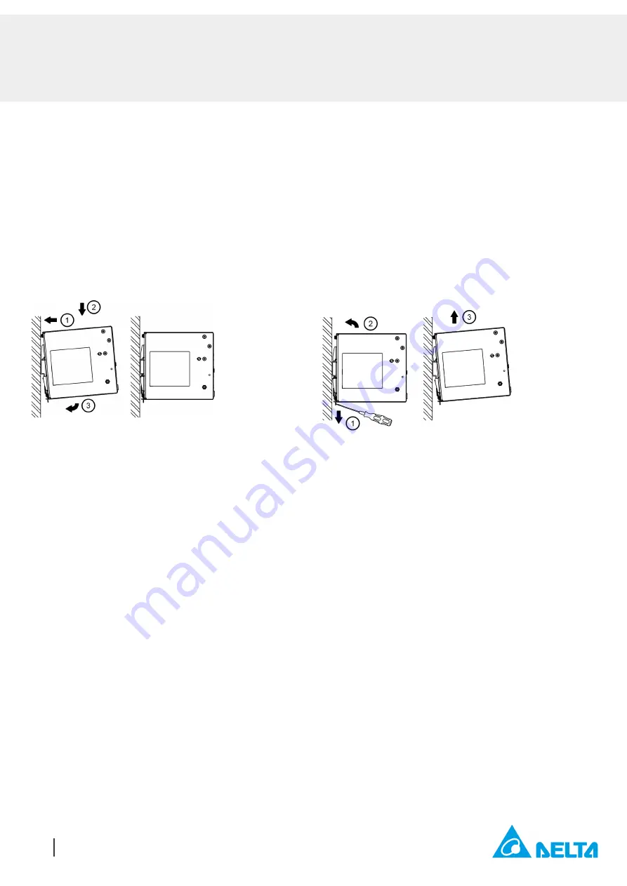
1.  Tilt the unit upwards and insert it onto the DIN rail. Snap on the DIN rail as shown in Fig. 3.1. 

2.  Push downwards until stopped. 

3.  Press against the bottom front side for locking. 

4.  Shake the unit slightly to ensure that it is secured. 

5.  To uninstall, pull or slide down the latch with screw driver as shown in Fig. 3.2. Then slide the power supply unit (PSU) in the opposite 

direction, release the latch and pull out the power supply unit (PSU) from the rail. 


Mounting 

Dismounting 


Fig. 3.1   Mounting 


Fig. 3.2   Dismounting 


In accordance to IEC/EN/UL/CSA 62368-1 and IEC/EN/UL/CSA 61010-2-201, flexible cables require ferrules.  

Use appropriate copper cables designed to sustain operating temperature of: 

  At least 75°C for ambient < 25°C 

  At least 90°C for ambient < 70°C.


Содержание FORCE-GT DRF-24V960W3GBA

Страница 1: ...al Description The Force GT Series DIN rail industrial power supply features high power density and high efficiency The Series offers overcurrent protection in constant current mode making it suitable for charging applications Conformal coating is applied on the PCBAs to protect against dust and pollutants often found in harsh industrial environments The Series electromagnetic radiated and conduct...

Страница 2: ...ut see power de rating on page 3 2 Power supply can operate at DC input Output Ratings Characteristics 3 Nominal Output Voltage 24 Vdc Factory Set Point Tolerance 24 Vdc 2 Output Voltage Adjustment Range 24 28 Vdc Output Current 0 40 0 A Output Power 960 W max Line Regulation 40 mV 3 x 320 575 Vac input 100 load Load Regulation 250 mV 3 x 320 575 Vac input 0 100 load PARD 4 20 MHz 200 mVpp Rise Ti...

Страница 3: ...f in The torque at the output terminal connector shall not exceed 19 7 Kgf cm 17 1 lbf in Environment Surrounding Air Temperature Operating 3 Phase 25 C to 70 C 40 C Cold Start 2 Phase 25 C to 60 C 40 C Cold Start Storage 40 C to 85 C Power De rating Vertical Mounting 55 C de rate power by 3 33 C Horizontal Mounting 25 C de rate power by 2 5 C Input Voltage 2 Phase 2 x 340 575 Vac de rate power to...

Страница 4: ...fe Time 10 Years I P 3 x 400 Vac 3 x 500 Vac O P 24 V 20 A Ta 40 C Safety Standards Directives Electrical Equipment of Machines EN BS EN 60204 1 over voltage category III Electrical Equipment for Use in Electrical Power Installations IEC EN BS EN 62477 1 IEC 62103 Safety Entry Low Voltage SELV IEC 60950 1 Electrical Safety SIQ Bauart EN 62368 1 EN 61010 1 EN 61010 2 201 EN 62477 1 UL cUL recognize...

Страница 5: ...c Fields IEC 61000 4 8 Level 4 Criteria A1 30 A m Voltage Dips and Interruptions IEC 61000 4 11 0 of 3 x 380 Vac 0 of 3 x 480 Vac 0 Vac 20 ms 0 Vac 20 ms Criteria A1 Criteria A1 40 of 2 x 380 Vac 40 of 2 x 480 Vac 70 of 2 x 380 Vac 70 of 2 x 480 Vac 0 152 Vac 200 ms 192 Vac 200 ms 266 Vac 500 ms 336 Vac 500 ms 0 Vac 5 000 ms Criteria A1 Criteria A1 Criteria A1 Criteria A1 Criteria B2 Low Energy Pu...

Страница 6: ... ambient and AC input 3x unless otherwise indicated www DeltaPSU com May 2022 Rev 00 6 Block Diagram Device Description 1 Input terminal block connector 2 Output terminal block connector 3 DC OK relay contact 4 DC voltage adjustment potentiometer 5 DC OK LED Green 6 QR code for product link 7 Universal mounting rail system ...

Страница 7: ...4 x 110 x 128 7 mm 4 88 x 4 33 x 5 07 inch AWG Wire Table Current Rating for PVC Wire 6 AWG 52 5 A 8 AWG 37 5 A 10 AWG 29 0 A 12 AWG 22 5 A 14 AWG 16 5 A 16 AWG 12 0 A 18 AWG 9 0 A 20 AWG 6 5 A 22 AWG 5 0 A 24 AWG 3 5 A 26 AWG 2 5 A 28 AWG 2 0 A 30 AWG 1 5 A Item Device Description 1 Input terminal block connector Pin 1 PE Pin 2 L1 Pin 3 L2 Pin 4 L3 2 Output terminal block connector Pin 1 to 2 V P...

Страница 8: ...as defined on Page 3 under Environment the device will run into Over Temperature Protection When activated the output voltage will go into bouncing mode and will recover when the surrounding air temperature is lowered or the load is reduced as far as necessary to keep the device in working condition 3 In order for the device to function in the manner intended it is also necessary to keep a safety ...

Страница 9: ...Snap on the DIN rail as shown in Fig 3 1 2 Push downwards until stopped 3 Press against the bottom front side for locking 4 Shake the unit slightly to ensure that it is secured 5 To uninstall pull or slide down the latch with screw driver as shown in Fig 3 2 Then slide the power supply unit PSU in the opposite direction release the latch and pull out the power supply unit PSU from the rail Mountin...

Страница 10: ...ing 80 mm 3 15 inch above and 40 mm 1 57 inch below the device as well as a lateral distance of 40 mm 1 57 inch to other units The external enclosure where the unit will be installed shall meet the requirements for mechanical electrical and fire enclosure Note that the enclosure of the device can become very hot depending on the surrounding air temperature and load of the power supply Risk of burn...

Страница 11: ...DC OK Relay Contacts and LED Indicator Characteristics DC OK Relay Contacts Status Characteristics Contact closes The output voltage 90 of its steady state set value Contact opens The output voltage 90 of its steady state set value Operating Status DC OK Green LED DC OK Relay Contact Normal Operation ON Closed Overload Hiccup Mode OFF Open Output Short Circuit OFF Open Over Temperature OFF Open No...

Страница 12: ... of its final steady state set value Hold up Time Time between the collapse of the AC input voltage and the output falling to 95 of its steady state set value Inrush Current Inrush current is the peak instantaneous input current measured and occurs when the input voltage is first applied For AC input voltages the maximum peak value of inrush current will occur during the first half cycle of the ap...

Страница 13: ...er the short circuit is removed Overvoltage Protection Auto Recovery The power supply s overvoltage circuit will be activated when its internal feedback circuit fails The output voltage shall not exceed its specifications defined on Page 4 under Protections Over Temperature Protection Auto Recovery As described in load de rating section the power supply also has Over Temperature Protection OTP In ...

Страница 14: ...ating Mode Fig 4 DC Input Operation Connection Diagram DC Input Operation Step 1 Use a battery or similar DC source Step 2 Connect either connections of pole and pole to L1 L2 L3 as below pole to L1 and pole to L2 pole to L1 and pole to L3 pole to L2 and pole to L1 pole to L2 and pole to L3 pole to L3 and pole to L1 pole to L3 and pole to L2 Step 3 Connect the PE terminal to an earth wire or to th...

Страница 15: ...on for any claim or action arising from any error for the provided information in the datasheets Customer shall take its responsibility for evaluation of using the product before placing an order with Delta Delta reserves the right to make changes to the information described in the datasheets without notice Manufacturer and Authorized Representatives Information Manufacturer Thailand Delta Electr...

Отзывы: