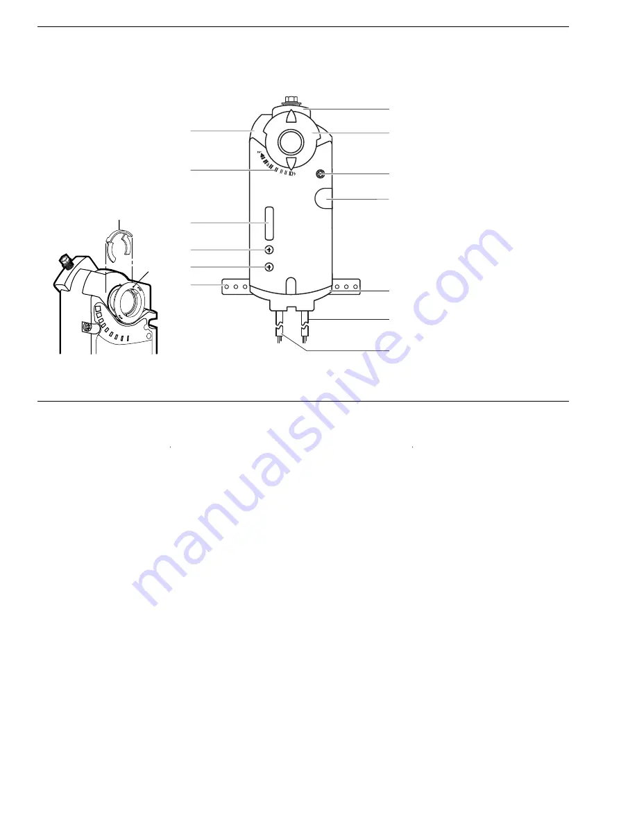
14
15
12
11
2
3
4
5
6
1
10
9
13
8
7
Legend
1. Actuator housing
2. Positioning scale for angle of
rotation
3. DIP switches and cover
4. Span adjustment
5. Offset (start point) adjustment
6. Mounting bracket
7. Connection cable for power
and control signals
8. Connection cable for auxiliary
switches or feedback potentiometer
9. Manual override
10. Auxiliary switches A & B
11. Position indicator
12. Self centering shaft adapter
13. 1/2-inch NSPT conduit
connection
14. Shaft adapter locking clip
15. Position indicator adapter
Figure 1. Non-Spring Return Actuator Components.
Actuator Components
Operation
DCM24-132 and DCM24-132-ZA
Apply a 0 to 10 Vdc control signal between wire 8 (Y) and wire 2 (G0) to operate the damper actuator. The angle of rotation
is proportional to the control signal. A 0 to 10 Vdc position feedback output signal is available between wire 9 (U) and
wire 2 (G0) to monitor the position of the damper motor. In the event of a power failure, the actuator holds its position. In
the event that only the control signal is lost, the actuator returns to the "0" position.
DC24-132-T,
DC24-132-TA
A floating control signal controls the damper actuator. The actuator’s angle of rotation is proportional to the length of
time the signal is applied. A 24 Vac control signal to wire 6 (Y1) causes the actuator coupling to rotate clockwise. A 24 Vac
control signal to wire 7 (Y2) causes the actuator coupling to rotate counterclockwise. To reverse the direction of rotation,
wires 6 (Y1) and 7 (Y2) can be interchanged. With no control voltage, the damper actuator holds its position.
Overload Protection
In the event of a blockage in the damper, the actuator is overload protected over the full rangeto prevent damage to the
actuator.
PAGE 3


