background image

15

BRUSH INSPECTION
AND REPLACEMENT

CAUTION: BEFORE INSPECTING THE BRUSH-
ES, DISCONNECT THE MACHINE FROM THE
POWER SOURCE.

Brush life varies. It depends on the load on
the motor. Check the brushes after the first 50
hours of use for a new machine or after a new
set of brushes has been installed. After the
first check, examine them after about 10
hours of use until such time that replacement
is necessary.

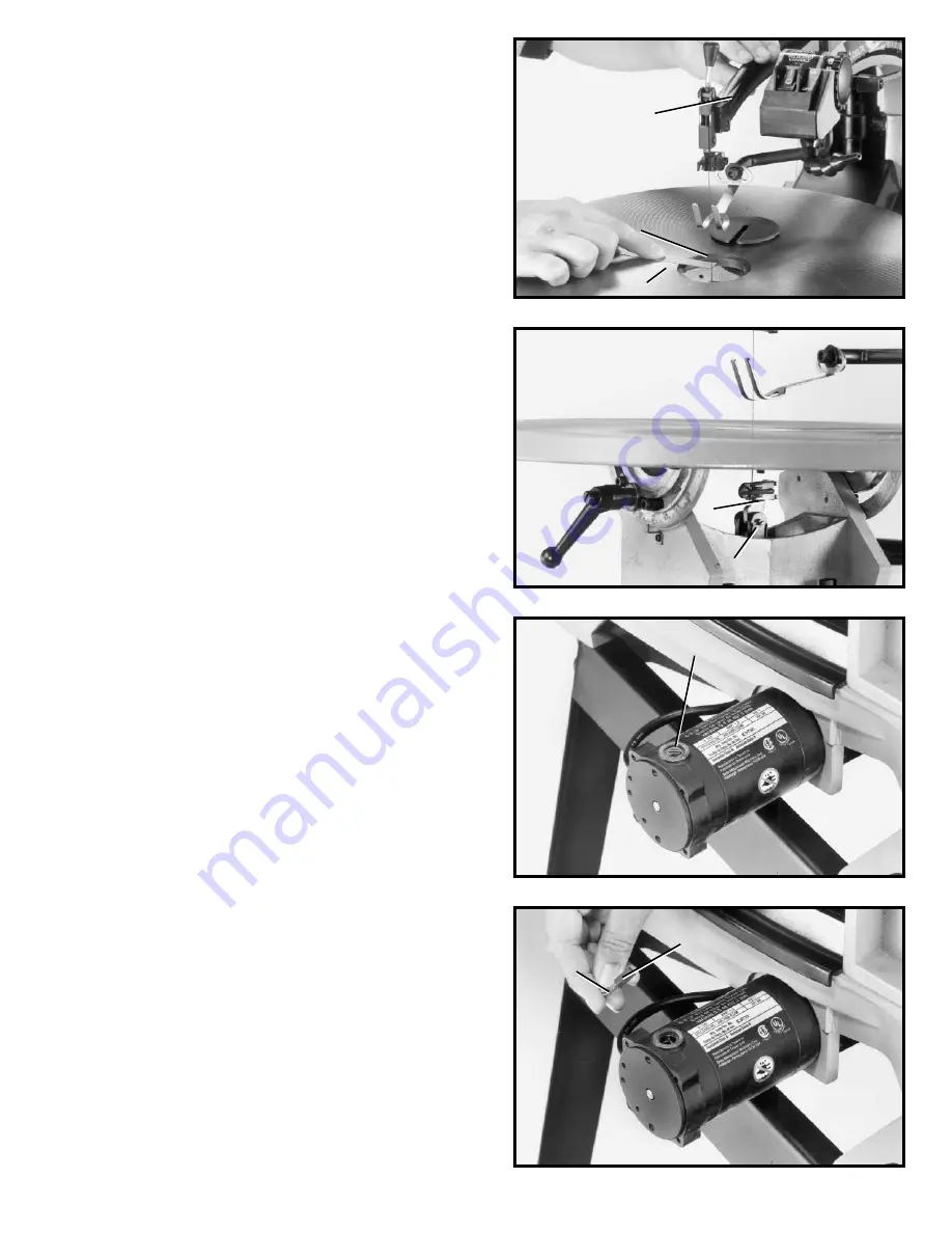
The brush holders, one of which is shown at
(A) Fig. 34, are located i-n the motor housing
opposite each other. Fig. 35 illustrates one of
the brushes removed for inspection. When the
carbon (B) on either brush is worn to 3/16" in
length or if either spring (C) or shunt wire is
burned or damaged in any way, replace both
brushes. If the brushes are found serviceable
after removing, reinstall them in the same
position as removed.

Fig. 32

Fig. 33

Fig. 34

Fig. 35

ALIGNING LOWER BLADE
HOLDER WITH UPPER
BLADE HOLDER

The lower blade holder has been aligned with
the upper blade holder at the factory and fur-
ther alignment should not be necessary; how-
ever, to check or adjust the alignment, pro-
ceed as follows:

1. MAKE CERTAIN THE MACHINE IS DIS-
CONNECTED FROM THE POWER SOURCE.

2. Remove the table insert and place a small
straight edge (A) Fig. 32, against the side of
the saw blade (B) as shown in Fig. 32.
3. While holding the straight edge (A) Fig. 32,
against the saw blade, carefully move the cut-
ting arm (E) up and down in a cutting motion.
CAUTION: Do not use excessive force on the
cutting arm. The saw blade should contact the
straight edge during the entire cutting stroke.
4. If an alignment is necessary, rotate adjust-
ment screw (C) Fig. 33, to move the lower
blade holder (D) left or right, until the saw
blade is in consistent contact with the straight
edge during the entire cutting stroke.

A

B

C

D

A

B

C

E

Содержание 40-650

Страница 1: ...1 DATED 11 25 98 INSTRUCTION MANUAL PART NO 1349463 Delta International Machinery Corp 1998 18 Variable Speed Scroll Saw Model 40 650 Type 2 Quick Quality Quiet ...

Страница 2: ...rds 9 Grounding Instructions 9 FASTENING STAND TO SUPPORTING SURFACE 10 OPERATING CONTROLS AND ADJUSTMENTS On Off Power Switch 10 Variable Speed Control 10 Locking On Off Switch In The OFF Position 10 Dust Blower 11 Adjusting Blade Tension 11 Adjusting Clamping Action Of Blade Holders 12 Adjusting Holddown 12 Changing Blades 13 Tilting The Table 14 Adjusting 90 And 45 Degree Positive Stops For Tab...

Страница 3: ...3 ...

Страница 4: ... while cutting Only feed the material fast enough so that the blade will cut 20 NEVER start the Scroll Saw with the stock pressed against the blade 21 WHEN cutting a large workpiece MAKE SURE the material is supported at table height 22 USE CAUTION when cutting material which is irregular in cross section which could pinch the blade before the cut is completed A piece of moulding for example must ...

Страница 5: ...aste wax Buff out the wax thoroughly to prevent it from rubbing into your workpieces 1 Scroll Saw 2 Holddown Foot 3 1 2 Long Hex Socket Head Screw for fastening holddown foot to rod 4 Lockwasher for fastening holddown foot to rod 5 Flat Washer for fastening holddown foot to rod 6 Table Insert 7 5mm Wrench 8 1 1 2 Long Hex Head Screws for fas tening front of saw to stand 2 9 Flat Washers for fasten...

Страница 6: ...aces DO NOT TIGHTEN STAND MOUNT ING HARDWARE AT THIS TIME ASSEMBLY INSTRUCTIONS WARNING FOR YOUR OWN SAFETY DO NOT CONNECT THE SCROLL SAW TO THE POWER SOURCE UNTIL THE MACHINE IS COMPLETELY ASSEMBLED AND YOU HAVE READ AND UNDERSTOOD THE ENTIRE OWNERS MANUAL 20 Height Adjustment Bracket for rear leg 21 Flat Washers 28 22 5 8 long 8mm Carriage Bolts 28 23 Hex Nuts 28 15 Bottom Shelf 16 Legs 3 17 Lef...

Страница 7: ...o 5 8 long screws F Fig 6 and lock washers G The 5 8 long screws F are also shown in Fig 7 and are threaded up into the threaded holes located on bottom of saw base FASTENING SCROLL SAW TO STAND 1 Place scroll saw on top braces of stand and fasten front of saw to top front brace using the two 1 1 2 long screws A Fig 5 flat washers B and two flat washers C lock washers D and hex nuts E from below B...

Страница 8: ...e rear leg of the stand as shown using the four carriage bolts B flat washers and nuts sup plied The height extension enables you to tilt the saw forward during operation if desired Five holes are supplied in the extension A to vary the degree of tilt ROTATING TABLE TO 90 DEGREE POSITION 1 The saw is shipped with the table tilted 45 degrees to the right as shown in Fig 11 To move the table to the ...

Страница 9: ...aged or worn cord immediately If a properly grounded outlet is not available a temporary adapter shown in Fig 15 may be used for connecting the 3 prong grounding type plug to a 2 prong receptacle The temporary adapter should be used only until a prop erly grounded outlet can be installed by a qualified elec trician The green colored rigid ear lug or the like extending from the adapter must be conn...

Страница 10: ...000 cutting strokes per minute by rotating control knob B Fig 16 With the control knob B rotated all the way toward the front of the machine the speed will be 300 cutting strokes per minute and with the control knob B rotated all the way to the rear the speed will be 2000 cutting strokes per minute A series of numbers are pro vided on the control knob as shown and a witness line C is provided on t...

Страница 11: ...ver A Fig 20 should be in the full forward position It is only necessary to adjust blade tension knob when a different type of blade is assembled to the blade holders It is not necessary to adjust blade tension when the blade is removed from and replaced in only the upper blade holder as in performing inside cutting operations Adjusting proper tension on the blade is usually accomplished by trial ...

Страница 12: ... 23 ADJUSTING HOLDDOWN 1 The holddown A Fig 23 should be adjusted so it contacts the top surface of the work being cut by loos ening lock handle B and moving holddown rod C up or down Then tighten lock handle B 2 When bevel cutting table tilted the holddown A Fig 23 can be tilted to match the angle of the table by loosening screw D tilting holddown A and tightening screw D 1 Move the blade holder ...

Страница 13: ... holders in the same manner making certain the blade teeth are pointing down toward the table 7 Apply blade tension by referring to section AD JUSTING BLADE TENSION NOTE NEVER push down on blade tension knob B Fig 25 to compress tension spring C E D CHANGING BLADES 1 WARNING TO AVOID INJURY FROM ACCIDENTAL STARTING ALWAYS TURN SWITCH OFF AND RE MOVE POWER CORD PLUG FROM ELECTRICAL OUT LET BEFORE R...

Страница 14: ...tighten table lock handle 5 Using a square D Fig 31 check to see if the table is 45 degrees to the saw blade as shown 6 If the table is not at 45 degrees to the blade adjust the table accordingly making certain screw E Fig 30 contacts side of base when the table is at 45 degrees to the blade TILTING THE TABLE 1 The table on your scroll saw can be tilted up to 45 degrees to the right for bevel cutt...

Страница 15: ...in the same position as removed Fig 32 Fig 33 Fig 34 Fig 35 ALIGNING LOWER BLADE HOLDER WITH UPPER BLADE HOLDER The lower blade holder has been aligned with the upper blade holder at the factory and fur ther alignment should not be necessary how ever to check or adjust the alignment pro ceed as follows 1 MAKE CERTAIN THE MACHINE IS DIS CONNECTED FROM THE POWER SOURCE 2 Remove the table insert and ...

Страница 16: ...es for hard materials or when a smoother cut is required 2 Use a coarser blade for cutting thick workpieces when making straight cuts or for medium to soft materials 3 Use a blade that will have 2 teeth in the workpiece at all times 4 Most blade packaging is marked with the size of the wood the blade is intended to cut and the minimum radius which can be cut with that blade 5 Slower speeds are gen...

Отзывы: