Delta 36-650 Скачать руководство пользователя страница 25

25

RIPPING

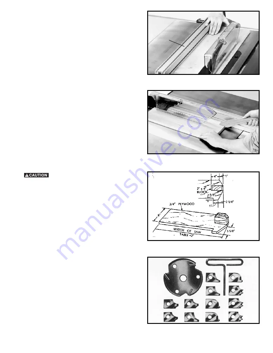
Ripping is the operation of making a lengthwise cut
through a board, as shown in Fig. 82, and the rip fence (A)
is used to position and guide the work. One edge of the
work rides against the rip fence while the flat side of the
board rests on the table. Since the work is pushed along
the fence, it must have a straight edge and make solid
contact with the table. The saw guard must be used. The
guard has anti-kickback fingers to prevent wood
kickback, and a splitter to prevent the wood kerf from
closing and binding the blade.

Start the motor and advance the work holding it down
and against the fence. Never stand in the line of the saw
cut when ripping. Hold the work and push it along the
fence and into the saw blade as shown in Fig. 82. The
work can then be fed through the saw blade with one or
two hands. After the work is beyond the saw blade and
anti-kickback fingers, the hand is removed from the work.
When this is done the work will either stay on the table,
tilt up slightly and be caught by the rear end of the guard
or slide off the table to the floor. Alternately, the feed can
continue to the end of the table, after which the work is
lifted and brought back along the outside edge of the
fence. The cut-off stock remains on the table and is not
touched with the hands until the saw blade is stopped,
unless it is a large piece allowing safe removal. When
ripping boards longer than three feet, it is recommended
that a work support be used at the rear of the saw to keep
the workpiece from falling off the saw table.

If the ripped work is less than 4 inches wide,

a push stick should always be used to complete the feed,
as shown in Fig. 83. The push stick can easily be made
from scrap material as explained in the section

“CONSTRUCTING A PUSH STICK.”

When ripping material under 2 inches in width, a flat
pushboard is a valuable accessory since ordinary type
sticks may interfere with the blade guard. That flat
pushboard can be made as shown in Fig. 83A.

USING ACCESSORY
MOULDING CUTTERHEAD

Moulding is cutting a shape on the edge or face of the
work. Cutting mouldings with a moulding cutterhead in
the circular saw is a fast, safe and clean operation. The
many different knife shapes available make it possible for
the operator to produce almost any kind of mouldings,
such as various styles of corner moulds, picture frames,
table edges, etc.

The moulding head consists of a cutterhead in which can
be mounted various shapes of steel knives, as shown in
Fig. 84. Each of the three knives in a set is fitted into a
groove in the cutterhead and securely clamped with a
screw. The knife grooves should be kept free of sawdust,
which would prevent the cutter from seating properly.

Fig. 82

A

Fig. 83A

Fig. 83

Fig. 84

Содержание 36-650

Страница 1: ...el 36 650 PART NO 902113 11 22 02 Copyright 2002 Delta Machinery To learn more about DELTA MACHINERY visit our website at www deltamachinery com For Parts Service Warranty or other Assistance please c...

Страница 2: ...will do the job better and be safer at the rate for which it was designed 10 USE RIGHT TOOL Don t force tool or attachment to do a job for which it was not designed 11 WEAR PROPER APPAREL No loose cl...

Страница 3: ...blade prior to release E never ripping a workpiece that is twisted or warped or does not have a straight edge to guide along the fence F using featherboards when the anti kickback device cannot be use...

Страница 4: ...nt ground such as a properly grounded outlet box Whenever the adapter is used it must be held in place with a metal screw NOTE In Canada the use of a temporary adapter is not permitted by the Canadian...

Страница 5: ...OR USE WITH STATIONARY ELECTRIC MACHINES Ampere Total Length Gauge of Rating Volts of Cord in Feet Extension Cord 0 6 120 up to 25 18 AWG 0 6 120 25 50 16 AWG 0 6 120 50 100 16 AWG 0 6 120 100 150 14...

Страница 6: ...10 Motor Pulley 11 Miter Gage Body 12 Miter Gage Guide Bar 13 Table Insert 14 Splitter Bracket 15 Blade Guard and Splitter Assembly 16 Saw Blade 17 7 8 Open End Wrench 18 7 8 and 1 2 Close End Wrench...

Страница 7: ...0x3 4 Hex Head Screw 2 9 7 16 Flat Washer 6 10 10mm Flat Washer 2 11 3 8 Flat Washer 8 12 21 64 Flat Washer 1 13 5 16 Flat Washer 37 14 1 4 Flat Washer 3 Fig 5 15 7 16 Lockwasher 6 16 3 8 Lockwasher 8...

Страница 8: ...HINE WE SUGGEST THAT THE STAND BE MOUNTED TO THE SAW AS FOLLOWS 1 Place the saw upside down on a sturdy work bench or floor as shown in Fig 8 TO PROTECT THE TABLE TOP PLACE SOMETHING BETWEEN THE TABLE...

Страница 9: ...stand mounting hardware Fig 10 BLADE TILTING AND RAISING HANDWHEEL 2 Assemble the blade raising handwheel A Fig 12 to the front of the saw in the same manner 1 Place blade tilting handwheel A Fig 11...

Страница 10: ...cabinet by turning screws E Fig 14 clockwise NOTE Cords will be adjusted later Place switch on top of the saw table at this time Fig 13 C B A Fig 14 B A D E C Fig 15 A B D RECOMMENDED MOTOR FOR YOUR S...

Страница 11: ...NOTE Do not completely tighten the hex nuts at this time Fig 16 A B C D E F MOTOR AND MOTOR MOUNTING PLATE TO SAW DISCONNECT MACHINE FROM POWER SOURCE 1 Insert a pin X Fig 17 into the holes in each s...

Страница 12: ...is centered and through the hole in the belt and pulley guard bracket G as shown in Fig 24 Tighten the four hex nuts that fasten the motor to the motor mounting plate 6 Using a straight edge align th...

Страница 13: ...THE LEFT UNTIL YOU ARE CERTAIN THE TOP J OF THE MOTOR IS BELOW THE TOP OF THE TABLE SURFACE THEN RE ALIGN THE MOTOR PULLEY TO THE ARBOR PULLEY 10 Align the hole in the outer cover D Fig 26 with the 1...

Страница 14: ...trunnion Repeat this process for the remaining hole Do not completely tighten the two screws B at this time 2 Raise saw arbor to its highest position Fig 29 B A Fig 30 C 3 Remove screw and large wash...

Страница 15: ...the hole in the rear splitter mounting bracket place a 5 16 flat washer onto the carriage head screw thread a 5 16 18 hex nut onto the carriage head screw and tighten securely IMPORTANT The splitter G...

Страница 16: ...blade guard when it is installed in the table opening Fig 37 G A Fig 38 L P EXTENSION WINGS 1 Assemble extension wing A Fig 39 to the saw table Align the three holes in the extension wing with the thr...

Страница 17: ...able square F Fig 44 or a ruler check to make certain the rear guide rail J is parallel with the saw table and extension tables GUIDE RAILS AND SWITCH ASSEMBLY 1 Loosely assemble front guide rail A Fi...

Страница 18: ...the fence B Fig 46 should line up so it is parallel with the edge of the miter gage slot If an adjustment is necessary tighten or loosen either of two screws D Fig 47 as necessary until rip fence B Fi...

Страница 19: ...dlock C with a 3 16 diameter shackle to prevent unauthorized use STARTING AND STOPPING SAW 1 The on off switch is located underneath the switch shield A Fig 54 To turn the saw ON move switch trigger B...

Страница 20: ...ade is not at 45 degrees to the table loosen set screw F Fig 59 and turn blade tilting handwheel until you are certain the blade is 45 degrees to the table Turn set screw F clockwise until it bottoms...

Страница 21: ...o loose or too tight an adjustment can be made by equally tightening or loosening two screws C as necessary NOTE It will be necessary to remove the cursor D Fig 64 to make this adjustment THE BLADE FL...

Страница 22: ...e into the miter gage bar B The miter gage is equipped with adjustable index stops at 90 degrees and 45 degrees right and left The index stops can be adjusted by tightening or loosening the three adju...

Страница 23: ...push the reset button A which will reset the overload device The motor can then be turned on again in the usual manner Fig 71 A CHANGING THE SAW BLADE USE ONLY 10 DIAMETER BLADES WITH 5 8 ARBOR HOLES...

Страница 24: ...rk are pulled back to the starting point Before pulling the work back it is good practice to give the work a little sideways shift to move the work slightly away from the saw blade Never pick up any s...

Страница 25: ...s not touched with the hands until the saw blade is stopped unless it is a large piece allowing safe removal When ripping boards longer than three feet it is recommended that a work support be used at...

Страница 26: ...ANDARD TABLE INSERT It is necessary when using the moulding cutterhead to add wood facing C to the face of the rip fence as shown in Fig 88 The wood facing is attached to the fence with fasteners as s...

Страница 27: ...e is cut by using the two outside saws The teeth of the saws should be positioned so that the raker on one saw is beside the cutting teeth on the other saw The dado head set D Fig 92 is assembled to t...

Страница 28: ...e rip fence and the saw table surface Fig 94 B B A CONSTRUCTING A FEATHERBOARD Fig 95 illustrates dimensions for making a typical featherboard The material which the featherboard is constructed of sho...

Страница 29: ...ERE TO PUSH 1 4 WOOD CUT OFF HERE TO PUSH 1 2 WOOD NOTCH TO HELP PREVENT HAND FROM SLIPPING 1 2 SQUARES CONSTRUCTING A PUSH STICK When ripping work less than 4 inches wide a push stick should be used...

Страница 30: ...s This warranty is Delta s sole warranty and sets forth the customer s exclusive remedy with respect to defective products all other warranties express or implied whether of merchantability fitness fo...

Страница 31: ...NOTES 31...

Страница 32: ...Southern Avenue Suite 105 Phone 602 437 1200 Fax 602 437 2200 CALIFORNIA Ontario 91761 Los Angeles 3949A East Guasti Road Phone 909 390 5555 Fax 909 390 5554 San Leandro 94577 Oakland 3039 Teagarden...

Отзывы: