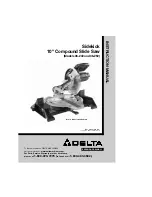
Delta 36-240 Скачать руководство пользователя страница 1

INSTRUCTION

MANUAL

Sidekick

10" Compound Slide Saw

(Models 36-240 and 36-250)

PART NO. 902096 (014)

Copyright © 2001 Delta Machinery

ESPAÑOL: PÁGINA 33

To learn more about DELTA MACHINERY 
visit our website at: 

www.deltamachinery.com.

For Parts, Service, Warranty or other Assistance,

please call 

1-800-223-7278 (

In Canada call

1-800-463-3582).

Bench Model 36-240 Shown

Содержание 36-240

Страница 1: ...ART NO 902096 014 Copyright 2001 Delta Machinery ESPA OL P GINA 33 To learn more about DELTA MACHINERY visit our website at www deltamachinery com For Parts Service Warranty or other Assistance please...

Страница 2: ...y are not safety glasses Also use face or dust mask if cutting operation is dusty These safety glasses must conform to ANSI Z87 1 requirements Note Approved glasses have Z87 printed or stamped on them...

Страница 3: ...ALLOW the motor to come up to full speed before starting cut 16 KEEP the motor air slots clean and free of chips 17 ALWAYS MAKE SURE all clamp handles are tight before cutting 18 BE SURE blade and bl...

Страница 4: ...AN CHECK THE RECEPTACLE 1 A l l g r o u n d e d c o r d c o n n e c t e d t o o l s In the event of a malfunction or breakdown grounding provides a path of least resistance for electric current to red...

Страница 5: ...n the down position until the machine is placed on a workbench or the stand model has been set in an upright position NOTICE THE MANUAL COVER PHOTO ILLUSTRATES THE CURRENT PRODUCTION MODEL ALL OTHER I...

Страница 6: ...6 250 Only 1 Tilt the machine on its right side and unfold right leg A as shown in Fig 5 2 Lift up and unfold left leg B Fig 6 and lock in place by pushing inward on leg hinges C ASSEMBLY Fig 6 1 Dust...

Страница 7: ...semblies two of which are shown at F Fig 8 6 With foot on lower brace G Fig 9 lift up table extension H so upper leg J extends out from lower leg K and protrusions L Fig 10 snap in and engage with rou...

Страница 8: ...15 MOVING CUTTINGHEAD TO THE REAR POSITION For models 36 240 and 36 250 1 MAKE CERTAIN THE TOOL IS DISCONNECTED FROM THE POWER SOURCE 2 Carefully remove cable tie A Fig 12 which is holding the cutting...

Страница 9: ...E CUTTINGHEAD 1 While holding the cuttinghead A Fig 17 down pull out and rotate cuttinghead lock knob B 90 degrees until pin C Fig 18 is in the horizontal position as shown The cuttinghead can then be...

Страница 10: ...le is in the locked position 3 For proper operation and adjustment of the table refer to sections ROTATING TABLE FOR MITER CUTTING ADJUSTING CLAMPING ACTION OF TABLE LOCKING MECHANISM and ADJUSTING SL...

Страница 11: ...THE ARBOR SCREW THE A R B O R S C R E W S H O U L D B E C H E C K E D PERIODICALLY AND TIGHTENED IF NECESSARY LOCKING SWITCH IN THE OFF POSITION IMPORTANT When the tool is not in use the switch should...

Страница 12: ...iate angles ADJUSTING CLAMPING ACTION OF TABLE LOCKING MECHANISM When rotating the table the table locking lever A Fig 33 must be compressed When the locking lever A is not compressed the table should...

Страница 13: ...nd the spring loaded positive stop for the 0 degree mark on the scale is engaged 3 Using a square A Fig 35 place one end of the square against the fence B and the other end against the blade as shown...

Страница 14: ...kpiece F IMPORTANT When lowering clamp A make certain cam lever G is in the up position as shown 3 For final clamping of the workpiece F Fig 40 against the table move cam lever G to the rear as shown...

Страница 15: ...on an indicator is provided on the bevel scale at the 33 9 degree bevel angle for cutting crown moulding Refer to the CUTTING CROWN MOULDING section of this manual When it becomes necessary to adjust...

Страница 16: ...de is 90 degrees to the table Then tighten locknut B 5 When you are certain blade is 90 degrees to table loosen screw J Fig 46 and adjust pointer H to line up with the 0 degree mark on bevel scale K 6...

Страница 17: ...sted at the factory in order that the cuttinghead returns to the up position after a cut has been made If it ever becomes necessary to re adjust the spring tension proceed as follows 1 Turn adjusting...

Страница 18: ...ce ADJUSTING SLIDING FIT BETWEEN GUIDE RODS AND TABLE ASSEMBLY To adjust the sliding fit between guide rods G Fig 50 and table assembly J remove lock knob H and loosen locknut K With wrenches provided...

Страница 19: ...ports just about any size of workpiece that fits into the saw An auxiliary fence C Fig 53 is provided on each table extension and should be adjusted in line with the saw fence E by loosening screw D a...

Страница 20: ...hile holding legs A as shown press spring loaded detents B with your thumbs and carefully lower upper legs Tighten locking knobs G Fig 55 3 Fig 56 illustrates the left leg C lowered Lower the right le...

Страница 21: ...aw horses or on 2 x 4 table extensions To remove the saw from the stand proceed as follows 1 Pull out extension tables A Fig 61 and lock in place 2 Position extension arms B on two saw horses as shown...

Страница 22: ...her side of the machine in the same manner 9 When using the saw on saw horses or 2 x 4 extensions See Figures 70 and 71 assemble the mounting feet M to the channels as shown in Fig 65 and tighten scre...

Страница 23: ...are shown at O Fig 66 and lock in place In this case it is not necessary to replace the table extensions J O O J FASTENING THE SAW TO A WORKBENCH FOR ALL MODELS Figs 67 and 68 illustrate the slide sa...

Страница 24: ...x 4 extensions Note that notches in the front and rear of the mounting feet K are designed to fit and fastened to the top of the two 2 x 4 s P The length of the two 2 x 4 s P can vary depending on yo...

Страница 25: ...TO KICK UPWARDS AND TOWARDS THE OPERATOR ALWAYS PUSH THE SAW FORWARD AWAY FROM THE OPERATOR AND TOWARDS THE FENCE WHEN SLIDE CUTTING The following steps illustrate the proper operating procedure to fo...

Страница 26: ...head C Fig 76 forward toward the fence making the cut as shown 5 Figure 77 illustrates the completed cut Release the switch trigger and keep the cuttinghead in the down position until the blade D come...

Страница 27: ...ocked in the rear position as shown in Fig 81 by tightening lock knob A when cutting material that is narrow enough to allow the saw blade to cut through in a chopping motion The cuttinghead B is push...

Страница 28: ...he outside corner will always be on the right hand side of the blade as shown at B Fig 83 The piece of crown moulding used for the inside corner will always be on the left side of the blade as shown a...

Страница 29: ...arbor from turning Remove screw E Fig 88 outside blade flange H and blade J DO NOT REMOVE INSIDE BLADE FLANGE 5 Make sure the inside surfaces of both the inside and outside blade flanges are clean and...

Страница 30: ...t check examine them after about 10 hours of use until such time that replacement is necessary The brush holders A Fig 90 are located on the motor housing opposite each other Fig 91 illustrates one of...

Страница 31: ...y is Delta s sole warranty and sets forth the customer s exclusive remedy with respect to defective products all other warranties express or implied whether of merchantability fitness for purpose or o...

Страница 32: ...32 NOTES...

Страница 33: ...9762 Fax 510 357 7939 FLORIDA Davie 33314 Miami 4343 South State Rd 7 441 Unit 107 Phone 954 321 6635 Fax 954 321 6638 Tampa 33609 4538 W Kennedy Boulevard Phone 813 877 9585 Fax 813 289 7948 GEORGIA...

Отзывы: