Delta 28-206 Скачать руководство пользователя страница 12

12

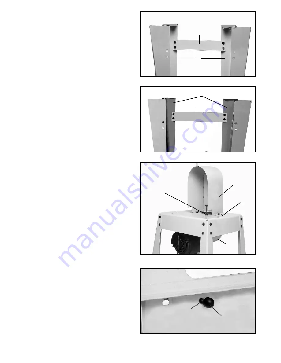
14. Align the four holes in the short brace (A) Fig. 14,
with the four holes in the two legs (B).

15. Insert a M8x1.25x16mm carriage head bolt through
the hole in the stand and the hole the short brace.

16. Thread a M8x1.25 flange nut onto the screw. 

NOTE:

DO NOT COMPLETELY TIGHTEN STAND HARDWARE
AT THIS TIME.

17. Repeat this process for the three remaining holes in
the short brace.

18. Attach the remaining short brace to the opposite
side of the stand in the same manner.

Fig. 14

Fig. 15

19. Align the four holes in the long brace (A) Fig. 15, with
the four holes in the two legs (B).

20. Insert a M8x1.25x16mm carriage head bolt through
the hole in the stand and the hole in the long brace.

21. Thread a M8x1.25 flange nut onto the screw. 

NOTE:

DO NOT COMPLETELY TIGHTEN STAND HARDWARE
AT THIS TIME.

22. Repeat this process for the three remaining holes in
the long brace.

23. Attach the remaining long brace to the opposite side
of the stand in the same manner.

24. Turn the stand over so that it is resting on its legs.

25. Thread a M8x1.25 hex nut onto a M8x1.25x80mm
hex head screw approximately 1/4".

26. Thread the M8x1.25x80mm hex head screw into the
hole (A) Fig. 16, in the top of the stand.

27. Place the damping cap (A) Fig. 16A onto the
threaded end of the screw (C).

28. Insert the two threaded studs on the lower pulley
guard (C) Fig 16, through the two holes  in the top of the
stand (B).

29. Align the two holes in the upper pulley guard (D) Fig.
16, with the two threaded studs on the lower pulley
guard (C). Place the upper pulley guard on the studs of
the lower pulley guard.

30. Thread an M8x1.25 hex flange nut onto each of the
studs and tighten securely.

31. Make sure the stand is level and tighten all stand
hardware at this time.

Fig. 16

A

B

A

C

B

D

A

B

Fig. 16A

A

C

Содержание 28-206

Страница 1: ...452 08 16 02 Copyright 2002 Delta Machinery ESPA OL P GINA 25 To learn more about DELTA MACHINERY visit our website at www deltamachinery com For Parts Service Warranty or other Assistance please call...

Страница 2: ...y to get caught in moving parts Nonslip footwear is recommended Wear protective hair covering to contain long hair 12 SECURE WORK Use clamps or a vise to hold work when practical It s safer than using...

Страница 3: ...surface against the table 13 HOLD WORKPIECE FIRMLY and feed into blade at a moderate speed 14 NEVER REACH UNDER THE TABLE while the machine is running 15 TURN THE MACHINE OFF to back out of an uncomp...

Страница 4: ...pter should be used only until a properly grounded outlet can be installed by a qualified electrician The green colored rigid ear lug and the like extending from the adapter must be connected to a per...

Страница 5: ...Rating Volts of Cord in Feet Extension Cord 0 6 120 up to 25 18 AWG 0 6 120 25 50 16 AWG 0 6 120 50 100 16 AWG 0 6 120 100 150 14 AWG 6 10 120 up to 25 18 AWG 6 10 120 25 50 16 AWG 6 10 120 50 100 14...

Страница 6: ...Motor Mounting Plate 7 M8x1 25x80mm 4 for assembling saw to stand 1 2 3 4 5 6 8 M8 Lockwasher 4 for assembling saw to stand 9 M8 Flat Washer 4 for assembling saw to stand 10 M8x1 25 Hex nut 4 for ass...

Страница 7: ...x1 25x16mm Hex Head Flange Screw 26 8 M8x1 25x16mm Round Head Flange Screw 4 Fig 3 9 M5x0 8x10mm Pan Head Screw 2 10 Shaft for attaching motor plate to top of stand 11 M8x1 25 Hex nut 12 Dampening Cap...

Страница 8: ...d 6 Lower Pulley Guard 7 M8x1 25x80mm Hex Head Screw 8 M8x1 25 Hex Nut Fig 4 9 Dampening Cap 10 M8x1 25x16mm Round Head Flange Screw 4 11 M8x1 25x16mm Carriage Head Screw 32 12 M8x1 25 Hex Flange Nut...

Страница 9: ...6 IS MOUNTED ON THE SIDE WITH THE BELT OPENING HOLE B 6 Insert a M8x1 25x16mm round head flange screw through the hole in the motor bracket and the hole in the motor mounting plate 7 Thread a M8x1 25...

Страница 10: ...ches B on the stand 21 Close the door until the door latch C Fig 9 engages with the side D 22 Attach the other door in the same manner Fig 9 Fig 10 23 Thread a M8x1 25 hex nut onto a M8x1 25x100mm hex...

Страница 11: ...AT THE MOTOR PULLEY A FIG 12 IS MOUNTED ON THE SIDE WITH THE BELT OPENING HOLE B 6 Insert a M8x1 25x16mm round head flange screw through the hole in the motor bracket and the hole in the motor mountin...

Страница 12: ...AT THIS TIME 22 Repeat this process for the three remaining holes in the long brace 23 Attach the remaining long brace to the opposite side of the stand in the same manner 24 Turn the stand over so t...

Страница 13: ...Place the belt over the saw pulley A Fig 18 NOTE THE MODEL 28 276 HAS ONLY A ONE STEP PULLEY THE MODEL 28 206 HAS A TWO STEP PULLEY AS SHOWN IN FIG 18 2 Lift the motor and place the other end of the...

Страница 14: ...door C 5 Make sure the quick tension lever D Fig 20 is positioned to the left of the machine 6 NOTE CHECK BLADE TO BE SURE TEETH WILL POINT DOWN TOWARD TABLE WHEN INSTALLED IF NOT TURN BLADE INSIDE O...

Страница 15: ...16 diameter shackle Fig 24 TILTING THE TABLE 1 The table on the band saw can be tilted 45 degrees to the right and 10 degrees to the left To tilt the table to the right loosen the two locking knobs A...

Страница 16: ...SCONNECT MACHINE FROM POWER SOURCE The Band Saw is equipped with a tension handle A Fig 28 To apply tension move the tension handle A Fig 28 to the right as shown To release the blade tension move the...

Страница 17: ...the blade guides and bearings according to the following instructions Set the upper blade guide assembly A Fig 33 as close as possible to the top surface of the workpiece Loosen the lock knob B and mo...

Страница 18: ...eccentric for the bearing 8 When the blade guide wears to a point that it cannot be adjusted close to the blade loosen screw B Fig 35 and reverse the blade guides A Fig 35 Fig 34 Fig 35 ADJUSTING LOW...

Страница 19: ...narrower blade a blade with more set or additional relief cuts Fig 39 may be necessary to allow the blade to cut more efficiently The more set a blade has the easier it will allow the stock to be tur...

Страница 20: ...position on flat level surface 3 Worn belt 3 Replace belt 4 Pulley not aligned 4 Adjust pulleys 5 Motor not fastened securely 5 Tighten all mounting hardware Trouble BAND SAW DOES NOT COME UP TO SPEED...

Страница 21: ...adjusted 3 Adjust blade support bearing 4 Blade wheel not tracking properly 4 Check and adjust blade tracking 5 Bad weld on blade 5 Replace the blade 6 Worn tires 6 Replace tires Trouble BAND SAW MAKE...

Страница 22: ...2 forcing or twisting a wide blade around a curve of short radius 3 feeding the work piece too fast into the blade 4 dullness of the teeth or absence of sufficient set 5 improperly tensioned blade 6...

Страница 23: ...23 NOTES...

Страница 24: ...s sole warranty and sets forth the customer s exclusive remedy with respect to defective products all other warranties express or implied whether of merchantability fitness for purpose or otherwise a...

Отзывы: